25
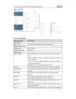
When more IP addresses are needed, set the
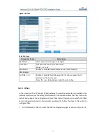
Multi link mode configuration
field to Enable
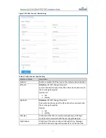
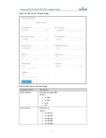
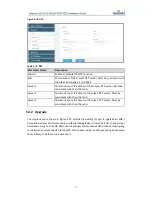
(Figure 5-4). Table 5-3 provides a description of each field.
Figure 5-4: Multi link mode configuration
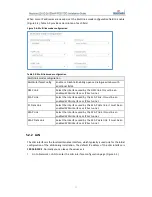
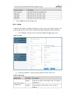
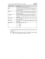
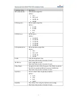
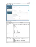
Table 5-3: Multi link mode configuration
Multi link mode configuration
MultiInterfacesConfig
Enable or Disable. Enabling opens a dialogue window with
additional fields.
OMC Link
Select the interface used by the OMC link. It must be an
enabled WAN interface or IPSec tunnel.
S1AP Link
Select the interface used by the S1 AP link. It must be an
enabled WAN interface or IPSec tunnel.
S1 Data Link
Select the interface used by the S1 AP data link. It must be an
enabled WAN interface or IPSec tunnel.
X2AP Link
Select the interface used by the X2 AP link. It must be an
enabled WAN interface or IPSec tunnel.
X2AP Data Link
Select the interface used by the X2 AP data link. It must be an
enabled WAN interface or IPSec tunnel.
5.2.2
LAN
The LAN interface is the local maintenance interface, which typically is used only for the initial
configuration of the eNB during installation. The default IP address of the LAN interface is
192.168.150.1
. Normally you can leave the values as is.
1.
Go to Network > LAN to enter the
LAN
interface configuration page (Figure 5-5).
Содержание Neutrino-224
Страница 1: ...Neutrino 224 Indoor 2x125mW FDD TDD eNodeB Installation Guide December 2018 Version 1 7...
Страница 20: ...20 Figure 4 7 FDD eNB GUI Home Page Figure 4 8 TDD eNB GUI Home Page...
Страница 47: ...47 Figure 5 24 LTE Neigh Freq Settings 1 of 2 Figure 5 25 LTE Neigh Freq Settings 2 of 2...
Страница 64: ...64 Figure 5 38 Cell ReSelection Parameter Figure 5 39 Additional Measurement Parameter...


