15.
Spare parts
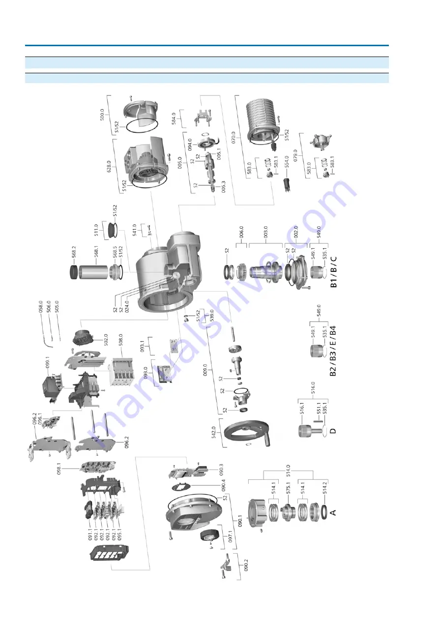
15.1.
Multi-turn actuators TR-M30X – TR-M1000X / TR-MR30X – TR-MR1000X
70
TR-M30X – TR-M1000X
TR-MR30X – TR-MR1000X
Страница 1: ...Multi turn actuators TIGRON TR M30X TR M1000X TR MR30X TR MR1000X Assembly and commissioning Operation instructions...
Страница 2: ...tor to valve 16 5 3 1 Overview of output drive types 16 5 3 2 Output drive type A 17 5 3 2 1 Multi turn actuator with output drive type A mount 19 5 3 2 2 Stem nut for output drive type A finish machi...
Страница 3: ...symbols in the display 52 10 1 1 Feedback signals from actuator and valve 54 10 1 2 Status indications according to AUMA classification 54 10 1 3 Status indications according to NAMUR recommendation 5...
Страница 4: ...74 Index 4 TR M30X TR M1000X Table of contents TR MR30X TR MR1000X...
Страница 5: ...be excluded at any time since they will lead to propagating brush discharges and therefore to ignition of a potentially explosive atmosphere This also applies to fireproof coatings or covers availabl...
Страница 6: ...ection Potentially explosive areas of zones 0 and 20 Potentially explosive areas of group I mining Radiation exposed areas in nuclear power plants No liability can be assumed for inappropriate or unin...
Страница 7: ...risk Failure to observe this warning could result in minor or moderate injury May also be used with property damage Potentially hazardous situation Failure to observe this warning could result in pro...
Страница 8: ...ormed at local controls using the Combi Switch The Combi Switch consists of two elements ab outer black selector switch and an inner yellow shuttle dial The display shows information on the actuator a...
Страница 9: ...oderate cost The AUMA Cloud collects all device data of all actuators within one site and provides a clear overview at a glance Detailed analysis provides valuable information on potential maintenance...
Страница 10: ...d power factor cos 12 Rated current 13 Type of duty 14 Motor protection temperature protection 15 Insulation class 16 Terminal plan and wiring diagram 17 Control 18 Can be assigned as an option upon c...
Страница 11: ...the operation instructions when entering the order number Actuator serial number Table 2 Description of serial number example of 0520MD12345 MD12345 20 05 Positions 1 2 Assembly in week week 05 05 Pos...
Страница 12: ...oks for the purpose of lifting by hoist only to the gearbox using eyebolts and NOT to the actuator Respect total weight of combination actuator gearbox valve Secure load against falling down sliding o...
Страница 13: ...ion Suspension with horizontal hollow shaft controls to bottom Figure 8 Examples left TR M30X right TR M500X 1 Suspension for sizes 30 60 120 2 Suspension for sizes 250 500 1000 Depending on the size...
Страница 14: ...or on a wooden pallet Cover to protect against dust and dirt Apply suitable corrosion protection agent to uncoated surfaces Risk of damage due to excessively low temperatures The actuator must may on...
Страница 15: ...shaft 3 Handwheel 4 Retaining ring How to proceed 1 If required fit spacer 1 on input shaft 2 2 Slip handwheel 3 onto input shaft 3 Secure handwheel 3 with retaining ring 4 Information The retaining...
Страница 16: ...ng valve stem not capable of withstanding thrust B B1 B4 C D 5 3 2 Output drive type A Figure 10 Output drive type A 1 Output mounting flange 2 Stem nut 3 Valve stem Short description Output drive typ...
Страница 17: ...Information For an unbored or pilot bore stem nut the stem nut must be finish machined prior to mounting valve stem and prior to performing the following steps page 19 Stem nut for output drive type A...
Страница 18: ...Fasten screws 3 crosswise with a torque according to table Table 7 Tightening torques for screws Tightening torque Nm Threads Strength class A2 80 A4 80 24 M8 48 M10 200 M16 392 M20 10 Turn multi tur...
Страница 19: ...with axial needle roller bearings 2 3 Remove axial bearing washers 2 1 and axial needle roller and cage assemblies 2 2 from stem nut 1 4 Drill and bore stem nut 1 and cut thread 5 Clean the machined...
Страница 20: ...ent output drive type is possible Output drive type B Output drive sleeve with bore according to DIN 3210 Output drive types B1 B3 Output drive sleeve with bore according to EN ISO 5210 Output drive t...
Страница 21: ...e to the valve or gearbox shaft 3 4 Place multi turn actuator 1 and ensure that the spigot fits uniformly in the recess and that the mounting faces are in complete contact 5 Fasten multi turn actuator...
Страница 22: ...tubes made of two or more segments 2 1 Seal threads of segments with hemp Teflon tape sealing agent or thread sealing material and fasten tightly 2 2 Push segments down to the sleeve connecting piece...
Страница 23: ...suitable approved insulation monitor measuring the pulse code is required Current type mains voltage mains fre quency Type of current mains voltage and mains frequency must match the data on the name...
Страница 24: ...le 10 Fuse for heating system Designation in wiring diagram F4 ext 230 V AC 115 V AC External power supply 1 A T 2 A T Fuse Risk of damage due to excessively low temperatures The power supply must be...
Страница 25: ...bles are laid close to the earth potential If possible avoid laying long cables and make sure that they are installed in areas being subject to low interference Avoid parallel paths with little cable...
Страница 26: ...ment open Figure 22 Open terminal compartment 1 Cover illustration shows KT version in type of protection Ex d 2 Screws for cover 3 O ring 4 Blanking plug 5 Cable gland example 6 KT Ex d connection fr...
Страница 27: ...wire per terminal Flexible 2 x 0 25 4 mm 2 for two wires per terminal Power contacts U1 V1 W1 U2 V2 W2 PE connection Spring clamp terminals Flexible or solid 0 25 2 5 mm 2 for one wire per terminal 2...
Страница 28: ...cables into spring clamp terminals 2 Tightening power terminals Information For service purposes each spring clamp terminal is equipped with a test contact located above the numbering Information For...
Страница 29: ...ive earth con ductor 6 Firmly tighten protective earth to PE connection M6 Figure 25 Protective earth connections within connection frame M6 Customer protective earth connection for M6 ring lug or wit...
Страница 30: ...O ring 3 is in good condition replace if damaged 4 Apply a thin film of non acidic grease e g petroleum jelly to the O ring and insert it correctly 5 Fit cover 1 and fasten screws 2 evenly crosswise...
Страница 31: ...oss sections and earth connection tightening torques Tightening torques Terminal cross sections Conductor type 3 4 Nm 2 5 mm to 6 mm Solid wire and stranded 3 4 Nm 1 5 mm to 4 mm Fine stranded For fin...
Страница 32: ...n The controls can be mounted separately from the actuator If the actuator cannot be accessed safely If the actuator is subjected to high temperatures In case of heavy vibration of the valve Informati...
Страница 33: ...tacts and against environmental influences Explosion hazard Risk of death or serious injury Prior to opening the device removing the plug ensure that the device is free of gas and voltage Do NOT switc...
Страница 34: ...confirm menu value Figure 33 For this turn selector switch briefly to the left or right and release again The selector switch toggles back into its initial position The toggle function is available fo...
Страница 35: ...enu Figure 36 If the ID of the indicated page starts with M PRM you have already entered the device menu How to proceed 1 Set selector switch to position OFF or REMOTE Figure 37 2 Turn selector switch...
Страница 36: ...or to go one step back ESC How to proceed 1 Open device menu Information If the ID of the indicated page starts with M PRM you have already entered the device menu For further information refer to pa...
Страница 37: ...rameter change cannot be executed with the current user level For this the display indicates the lowest required user level for performing changes Figure 43 Change user level example at least level 4...
Страница 38: ...entered the device menu For further information refer to page 35 Open device menu 2 Set user level 4 or higher page 37 Change user level 3 Select menu Change passwords M0229 Device configuration M005...
Страница 39: ...ted value e g Deutsch using If required select user level and enter the password For further informa tion refer to page 37 Change user level The display indicates parameter PRM0033 for selecting furth...
Страница 40: ...within the menu Operate the black selector switch outer ring either to confirm the selected menu or to go one step back ESC How to proceed 1 Open device menu Information If the ID of the indicated pa...
Страница 41: ...e menu 2 Select menu M0086 or M0087 Customer settings M0041 Type of seating M0012 End position CLOSED M0086 End position OPEN M0087 The display shows parameter PRM0578 or PRM009 Figure 49 For user lev...
Страница 42: ...witching M0013 Trip torque CLOSE M0088 Trip torque OPEN M0089 Information If required change user level For performing settings at least user level 4 is required For further information refer to page...
Страница 43: ...rmation refer to page 35 Open device menu 2 Select menu M0084 or M0085 Customer settings M0041 Limit switches M0010 Set end pos CLOSED M0084 Set end pos OPEN M0085 Figure 52 Information If required ch...
Страница 44: ...osition CLOSED The display indicates End pos CLOSED set and the right LED standard ver sion is illuminated Now the end position CLOSED of the limit switching is set Figure 54 8 If the setting must be...
Страница 45: ...00X Example Stroke 5 turns value per turn 120 461 Setting value 5 x 120 461 600 14 Set the value using Figure 56 15 Save new end position via Enter The signal End pos OPEN set or End pos CLOSED set is...
Страница 46: ...ta tion 1 Move actuator manually to intermediate position or to sufficient distance from end position 2 Depending on the version Unscrew threaded plug 1 with seal 2 protective cap 4 or stem protection...
Страница 47: ...tion OPEN the indication lights go out after travelling into the opposite direction The limit switching is set incorrectly if the actuator comes to a standstill before reaching the end position one of...
Страница 48: ...heel in desired direction Figure 58 The valve closing and opening directions are marked on the handwheel Table 16 Example for clockwise closing For valve opening turn handwheel in direc tion of the ar...
Страница 49: ...0 Actuator control from Remote Valve damage due to incorrect basic setting Prior to electric actuator operation perform the basic settings for type of seating and torque switching 9 2 1 Operation comm...
Страница 50: ...mode Remote via I O interface Symbol for operation mode Remote via fieldbus channel 1 Risk of immediate actuator operation when switching on Risk of personal injuries or damage to the valve If the ac...
Страница 51: ...ocal controls disabled Setpoint control EMERGENCY Failure behaviour fail safe PID Service 2 Status Information Warnings Out of specification Fault Failure 3 User User level 1 6 4 ID number of current...
Страница 52: ...ollowing information on the valve The applied torque appears as bar chart left Standard unit Nm selection available between ft lb and via menu Torque unit M0051 Valve position between 0 100 of travel...
Страница 53: ...hart left and as figure Standard unit Nm selection available between ft lb and via menu Torque unit M0051 Valve position or actual value E2 between 0 100 of travel as bar chart right or as figure in t...
Страница 54: ...avigation line is masked at the bottom of the display For further information on status indications refer to page 58 Fault indications and warning indications 10 1 3 Status indications according to NA...
Страница 55: ...ns can be assigned to LEDs 1 5 Device configuration M0053 Local controls M0159 Indication light 1 left M0093 Indication light 2 M0094 Indication light 3 M0095 Indication light 4 M0096 Indicat light 5...
Страница 56: ...lector sw REMOTE Signal DOUT 5 Torque fault CLOSE Signal DOUT 6 Torque fault OPEN 11 1 2 Output coding The output signalsCoding DOUT 1 Coding DOUT 12 can be set either to high active or low active Hig...
Страница 57: ...respective interface Please refer to www auma com for more information on the different communication systems On the internet the respective general station description files for device integration ar...
Страница 58: ...g Instead of the valve position a status text is dis played S0001 For indicated value 0 Toggle selector switch in direction For details refer to page 59 Table 20 Collective signal 02 Indicates the num...
Страница 59: ...gnal setpoint position Possible causes For an adjusted setpoint range of e g 4 20 mA the input signal is 0 signal loss For a setpoint range of 0 20 mA monitoring is not possible Wrn setpoint position...
Страница 60: ...dbus Torque fault in direction CLOSE Torque fault CLOSE Perform one of the following measures Issue operation command in direction CLOSE Position selector switch to LOCAL and reset fault signal by tog...
Страница 61: ...CLOSE simultaneously or OPEN and SET POINT operation simultaneously A setpoint is present and the positioner is not active Wrong oper cmd Set selector switch to REMOTE Selector switch is not in positi...
Страница 62: ...r voltage Is also used for AOUT 12 3 2 Motor protection thermal monitoring In order to protect against overheating and impermissibly high surface temperatures at the actuator PTC thermistors or thermo...
Страница 63: ...protection signal via the menu Required user level Specialist 4 or higher Diagnostics M0022 TMS proof test M1950 Test procedure 1 Set selector switch to OFF 2 Return to the main menu and select the s...
Страница 64: ...seals must be replaced in case of leakage When deployed in areas where dust formation represents a potential explosion hazard perform visual inspection for deposit of dirt or dust on a regular basis...
Страница 65: ...ding to manufacturer s details If required replace the components Only use components having an own EU type exam ination certificate or IECEx certification Check whether Ex connections are fastened co...
Страница 66: ...50 60 60 60 50 50 60 50 60 50 Hz Special voltages 3 phase AC Voltages frequencies 660 600 575 525 230 220 220 Volt 50 60 60 50 50 60 50 Hz Further voltages on request Permissible variation of mains vo...
Страница 67: ...uator position setpoint as continuous value from 0 4 20 mA Analogue input 24 V DC current consumption approx 10 mA per input Standard Control voltage current consumption for digital control inputs All...
Страница 68: ...operation mode adjustable generates warning signal Operation time monitoring adjustable generates warning signal Phase failure monitoring results in switching off and generates fault signal Rotary di...
Страница 69: ...A silver grey similar to RAL 7037 Standard Colour Available colours on request Options AUMA multi turn actuators meet or exceed the lifetime requirements of EN 15714 2 Detailed information can be prov...
Страница 70: ...15 Spare parts 15 1 Multi turn actuators TR M30X TR M1000X TR MR30X TR MR1000X 70 TR M30X TR M1000X Spare parts TR MR30X TR MR1000X...
Страница 71: ...motors 079 0 Sub assembly Screw plug 539 0 Sub assembly Cover for local controls assy 090 1 Sub assembly External earth connection 541 0 Sub assembly Locking device assy 090 2 Sub assembly Handwheel...
Страница 72: ...72 TR M30X TR M1000X TR MR30X TR MR1000X...
Страница 73: ...73 TR M30X TR M1000X TR MR30X TR MR1000X...
Страница 74: ...EMC 25 Enclosure protection 10 10 F Fault 58 Flange size 11 Fuses 62 G GSD file 57 H Handwheel 15 Heating system 24 Hollow shaft 46 I Indication lights 55 Indications 51 51 Input current 11 Input sign...
Страница 75: ...g 64 Setpoint 53 Short circuit protection 23 Signals 56 Signals analogue 56 Size 11 Spare parts 70 Speed 10 10 Standards 5 Status signals 56 Status signals Potential 24 Stem 46 Stem nut 19 Stem protec...
Страница 76: ...er GmbH Co KG P O Box 1362 DE 79373 Muellheim Tel 49 7631 809 0 Fax 49 7631 809 1250 info auma com www auma com Y009 100 003 en 1 21 For detailed information on AUMA products refer to the Internet www...