


4.5.1.
Profibus DP-V2 redundancy
The behaviour and the states of a redundant slave are defined in the "Specification
Slave Redundancy 2.212" (also refer to <Redundant behaviour according to Profibus
DP-V2 redundancy (PNO guideline 2.212)>). A distinction is made between a primary
and a backup channel, with different effects on the properties of Profibus DP
communication:
●
Cyclic Profibus DP-V0 communication
-
Operation commands of the primary channel are processed and executed
by the actuator; operation commands by the backup channel are ignored,
the communication for the backup channel is only used for monitoring.
-
Feedback signals of the actuator can be sent via both channels.
-
Diagnostic feedback signals of the primary channel contain diagnostic
status data of both the primary and the backup channel.
●
Acyclic Profibus DP-V1 services of the controls (DPM1 = master class 1) are
only supported by the primary channel.
●
Acyclic Profibus DP-V1 services of the engineering stations (DPM2 = master
class 2) are only supported by the primary channel.
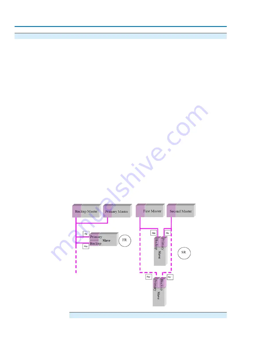
Furthermore, a distinction is made between two configuration types within the Profibus
DP-V2 redundancy:
Flying redundancy (FR)
●
The slave address of the primary channel is different from the address of the
backup channel (slave address backup = slave address p 64, for this
reason the slave address of the primary must be < 62).
●
Only the slave address of the primary channel has to be set.
●
The master never communicates via the backup channel with the slave.
System redundancy (SR)
●
The slave address of the primary channel corresponds to the slave address of
the backup channel.
●
The master can configure both channels and can establish a cyclic DP-V0
connection via both channels.
Figure 4: Configuration type for Profibus DP-V2
Setting the bus address (slave address)
Each channel has its own address. After setting the primary address, the backup
automatically accepts the address of the primary plus a configurable offset (either 0
or 64).
46
Actuator controls
Description of the data interface
AC(V) 01.2/AC(V)ExC 01.2 Profibus DP
Содержание AC(V) 01.2
Страница 1: ...Actuator controls AC V 01 2 AC V ExC 01 2 Profibus DP Device integration Manual...
Страница 22: ...22 Actuator controls Description of the data interface AC V 01 2 AC V ExC 01 2 Profibus DP...
Страница 89: ...89 Actuator controls AC V 01 2 AC V ExC 01 2 Profibus DP...
Страница 90: ...90 Actuator controls AC V 01 2 AC V ExC 01 2 Profibus DP...


