background image


Illustrated Parts List 


51 


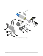
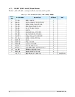
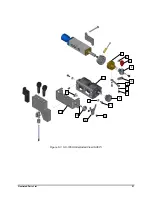
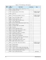
Figure 6-3   SC-105HS Exploded View (0-360°) 


12 

10 

11 

13 

14 

15 

16 

17 

Содержание Nordson Select Coat SC-100 Series

Страница 1: ...Select Coat SC 104HS SC 105HS Series Circulating Film Coater Owner s Manual ...

Страница 2: ...on comments and inquiries about its products Please contact us using the information below Headquarters 2762 Loker Avenue West Carlsbad CA 92010 6603 USA Toll Free 1 800 ASYMTEK 1 800 279 6835 Tel 1 760 431 1919 Fax 1 760 431 2678 E mail info asymtek com Website www asymtek com Technical Support USA 1 800 ASYMTEK 1 800 279 6835 Other regions www asymtek com Tech Support Trademarks Asymtek Century ...

Страница 3: ...Hydrocarbon Solvent Hazards 6 2 4 Disposal 6 2 5 Emergency Shutdown 6 2 6 Safety Warning Labels 7 3 Operation 8 3 1 Overview 8 3 2 Safety First 8 3 3 Theory of Operation 8 3 4 SC 10X Features 9 3 5 Feature Description 11 3 5 1 Micro Adjustment 11 3 5 2 Air Inlet 11 3 5 3 0 90 Rotate Mechanism Fourth Axis 11 3 5 4 Rotate and Tilt Mechanism Fifth Axis 11 3 5 5 Piston and Needle 11 3 5 6 Fluid 11 3 5...

Страница 4: ... Attaching the Film Coater to the Manifold 37 4 6 8 Installing the Solenoid Valve 37 4 6 9 Attaching the Film Coater to the Robot 38 4 6 10 Resetting the Micro Adjustment 38 4 7 Testing the Film Coater 38 5 Troubleshooting 39 5 1 Introduction 39 5 2 Safety First 39 5 3 Record Keeping 39 5 4 Troubleshooting the Film Coater 40 6 Illustrated Parts List 43 6 1 Overview 43 6 2 Safety First 43 6 3 Recor...

Страница 5: ...sassembling the Manifold SC 10X 26 Figure 4 6 Installing the U cup and Seals 27 Figure 4 7 Forming and Installing the Hat Seals 28 Figure 4 8 Installing the Bushing and Extension 29 Figure 4 9 Installing the Air Piston 31 Figure 4 10 Unacceptable Film Patterns 32 Figure 4 11 Adjusting the Spring Washers 33 Figure 4 12 Adjusting Preload Tension 34 Figure 4 13 Installing the Rotate Pulley SC 104 35 ...

Страница 6: ...ing 40 Table 6 1 SC 10X Parts List 46 Table 6 2 SC 104 Parts List 0 90 Rotate 48 Table 6 3 SC 105 Parts List 0 360 Dual Cylinder Rotate 50 Table 6 4 SC 105 Century C 74X Systems 52 Table 6 5 Service Kit Parts List P N 139745 54 Table 6 6 Nozzles 56 Table 6 7 Nozzle Cleaning Kit 56 Table 6 8 Broaches 56 Table 6 9 Nozzle Brush 57 Table 6 10 Nozzle Seal Tool 57 ...

Страница 7: ...ntury and Select Coat Series Conformal Coating Systems Coating programs are designed and the SC 100 Series coaters are operated with Asymtek s Easy Coat for Windows software This section covers the following topics Models Specifications Dimensions 1 2 Models There are two models available Table 1 1 SC 100 Series Coating Applicator Models Coating Applicator Rotation Tilt SC 104HS High Speed Film Co...

Страница 8: ...05 mm Masking Required No Material Viscosity Under 100 cps Application thickness 0 5 to 8 mils for solvent based materials and 4 to 8 mils for 100 percent solids materials Edge Tolerance 030 in 762 mm Transfer Efficiency Over 99 Coating Velocity 5 20 ips 13 51 cms Typical Fluid Dispense Pressure 15 60 psi 103 413 kPa Pattern Width 0 25 to 0 75 in 6 35 to 19 05 mm Pressure bar psi Maximum fluid Fil...

Страница 9: ... Dimensions Figure 1 2 Approximate Film Coater Dimensions NOTE Film coater extends from robot mounting surface approximately 5 715 cm 2 25 inch 10 475 cm 4 125 in 27 3 cm 10 75 in Front View Side View 10 475 cm 4 125 in ...

Страница 10: ...ser or damage to the coating system NOTE Safety is considered a joint responsibility between the original equipment manufacturer Asymtek and the end user owner All safety precautions and practices should be in accordance with local regulations and facility policy 2 2 Intended Use Use of Asymtek equipment in ways other than those described in the documentation supplied with the equipment may result...

Страница 11: ...wer sources are safely grounded Routinely inspect all air hoses and electrical cables for damage Make sure power cords and air supply hoses do not cross a walkway or aisle Maintain a clean and orderly work area 2 3 2 Material Safety Follow Material Safety Data Sheet MSDS recommendations for the proper handling cleanup and disposal of all materials and fluids and their containers i e syringes cups ...

Страница 12: ... skin can cause toxic poisoning If you suffer a fluid injection injury seek medical care immediately If possible provide a copy of the MSDS for the injected fluid to the health care provider 2 3 5 Halogenated Hydrocarbon Solvent Hazards Do not use halogenated hydrocarbon solvents in a pressurized system that contains aluminum components Under pressure these solvents can react with aluminum and exp...

Страница 13: ... label warns of moving parts that can cause serious injury to hands and fingers Disconnect and lock out power before servicing Heavy Object Lifting Hazard 70 0118 00 1 or 196666 2 This label warns that the labeled component is heavy and can cause muscle strain or back injury to personnel trying to lift it Hot Surface 70 0121 00 1 or 70 2150 00 2 Thermal warning labels identify potentially hot comp...

Страница 14: ...ta Sheet MSDS for all fluids used with the dispensing system The MSDS provides material usage instructions disposal instructions and safety precautions CAUTION Do not expose the solenoid valve to solvents or coating material Solvents could damage the valve and coating material may clog it 3 3 Theory of Operation The SC 100HS film coater is moved by a gantry robot horizontally along the X and Y axe...

Страница 15: ...5HS film coaters See 3 5 Feature Description for a description of the features Item Description Item Description 1 Micro Adjustment 5 Nozzle 2 Air In 6 Fluid Inlet 3 RTD Viscosity Control System Only 7 Fluid Outlet 4 0 90 Rotate Mechanism 8 Solenoid Valve Figure 3 1 SC 104HS Film Coater 1 4 5 2 3 6 7 8 ...

Страница 16: ...Item Description 1 Micro Adjustment 6 Nozzle See Table 6 6 2 Air Inlet 7 Fluid Inlet 3 RTD Viscosity Control System Only 8 Fluid Outlet 4 4 Position Rotate Assembly 9 Solenoid Valve 5 Tilt Linkage 10 Tilt Cylinder Figure 3 2 SC 105HS Film Coater 1 6 7 8 9 4 2 3 5 10 ...

Страница 17: ...re coupled together to provide four 90 indexed positions Air activates a cylinder located on the manifold causing the tilt mechanism to activate The cylinder arm extends or retracts moving a sleeve on the extension up or down This motion is transferred to the tilt lever which tilts the nozzle from 0 to 30 3 5 5 Piston and Needle The piston is forced upward by the trigger air until it comes in cont...

Страница 18: ... Description Item Description 1 Micro adjustment Cap Screw 5 Fluid Outlet 2 Spring Washers 6 Fluid Inlet 3 Piston 7 Needle 4 Air Inlet 8 Seat Figure 3 3 SC 10X Cross Section Fourth and Fifth Axes Removed 1 2 3 4 5 6 7 8 ...

Страница 19: ...in running this routine or writing a customized routine refer to the Easy Coat User Guide or contact your Asymtek representative 3 Place a small waste container under the end of the extension to catch coating material 4 Start the Easy Coat for Windows XP software 5 Start the purge program If the film coater is equipped with a tilt mechanism SC 105 operate the tilt mechanism several times while pur...

Страница 20: ...k nozzle brush to scrub the nozzle Do not use a steel brush or any other type of brush that will damage the nozzle carbide tip NOTES If the nozzle orifices are blocked insert a probe or broach into the orifice against the direction of fluid flow Do not twist the probe or broach or try to clean the orifice with a sawing motion If the nozzle nozzle nut or tilt mechanism are not properly cleaned coat...

Страница 21: ...al that every person servicing or operating the coating applicator fully understands all hazards risks and safety precautions Refer to Section 2 Safety for additional information WARNING Allow only qualified personnel to perform the following tasks Follow the safety instructions in this document and all other related documentation CAUTION Obtain and read Material Safety Data Sheets MSDS for all ma...

Страница 22: ...te solvent Refer to 3 6 Startup and 3 7 Shutdown for detailed instructions Clean and Inspect Film Coater As Needed 1 Remove the film coater from the robot and manifold Separate the lower body module from the upper body module 2 Remove the three O rings from the backside of the film coater Soak the extension and lower body module in the solvent used with the coating material Clean and dry the exten...

Страница 23: ...ing for Disassembly To prepare for disassembly 1 Run the purge program See 3 6 Startup WARNING System or material pressurized Relieve pressure Failure to do so may result in personal injury or equipment damage 2 Pull up on the relief valve on the fluid reservoir to relieve system pressure before opening the fluid reservoir Refer to the appropriate coating system manual for procedures 3 Drain coati...

Страница 24: ...lure To remove the film coater from the robot and manifold 1 Disconnect the air line and fluid line from the manifold 2 Unplug the electrical connector from the solenoid valve 3 Remove the screws securing the manifold to the Z axis slide 4 Remove the screws and film coater holder from the manifold 5 Tug gently on the film coater to disengage it from the tilt fork 6 Lift the film coater up and off ...

Страница 25: ...scription Item Description 1 Film Coater 5 Solenoid Valve 2 Mounting Screw 6 Fluid Outlet 3 Tilt Mechanism 7 Fluid Inlet 4 Manifold 8 O Rings 3 Figure 4 1 Removing the Film Coater from the Robot and Manifold SC 105 shown 5 1 8 2 3 4 6 7 ...

Страница 26: ...len wrench remove the set screw from the tilt lever 5 Pull the tilt lever from the nozzle holder 6 Keeping the nozzle port visible through the swivel base opening pull the nozzle holder from the swivel base 7 Inspect the Chemraz O ring in the needle holder for nicks Replace the O ring only if necessary 8 Soak the swivel base and nozzle holder in the appropriate solvent 9 Pull the bearing shifter f...

Страница 27: ...er 2 Upper Body Module 9 Swivel Base 3 Lower Body Module 10 Tilt Lever 4 Extension 11 Tilt Link 5 Rotate Pulley 12 Socket Cap Screw 6 Shifter Bearing 13 Unthreaded Clamp 7 Chemraz O ring 14 Threaded Clamp Figure 4 2 Tilt Mechanism and Rotate Pulley SC 105 shown 1 2 3 4 5 6 7 9 8 10 11 12 13 14 ...

Страница 28: ... 3 Remove the four screws securing the film coater cap to the top of the upper body module and remove the cap 4 Remove the four screws from the bronze bushing at the extension end of the film coater Remove the bushing and extension from the film coater 5 Remove the O ring and Teflon washer from the lower body module 6 Inspect the O ring and washer Replace them if necessary 7 Separate the upper and...

Страница 29: ...iption 1 Micro adjustment 5 Bronze Bushing 2 Screws 6 32 X 625 4 6 Screws 6 32 X 2 500 4 3 Applicator Cap 7 Lower Body Module 4 Extension 8 Upper Body Module Figure 4 3 Removing the Micro Adjustment Cap Film Coater Cap and Extension SC 104 1 2 3 4 7 6 8 5 ...

Страница 30: ...Place the pronged end of the ring and seal removal tool supplied with the service kit under one of the tabs of the retaining ring Gently lift the tab to loosen the retaining ring The retaining ring will pop free Inspect the retaining ring and replace it if it is damaged 4 Remove the backup seal and two hat seals from the upper body module Inspect the seals Replace them if they are damaged or if ai...

Страница 31: ...ion 1 Hex Nut 7 Backup Seal 2 Seal Lock Nut 8 Hat Seals 3 O Ring 9 Upper Body Module 4 Air Piston 10 U Cup Fluid Seal 5 Needle 11 Flat Washer 6 Retaining Ring 12 Retaining Ring Figure 4 4 Removing the Needle Piston and Seals SC 10X 1 2 3 4 5 6 8 7 9 10 11 12 ...

Страница 32: ...d CAUTION Protect the solenoid valve from contact with coating material or solvent Contamination could cause solenoid failure 3 Remove the solenoid valve from the manifold Inspect the solenoid gasket If the gasket is damaged replace the entire solenoid valve Item Description Item Description 1 Fluid Inlet and Outlet Fittings 5 Fitting Tube 2 Manifold 6 Fitting Union 3 RTD Probe 7 Solenoid Valve 4 ...

Страница 33: ...g up into the upper body module Do not snap the U cup into place at this time 2 Place the flat washer into the upper body module on top of the U cup Push on the washer with the base tool to seat the U cup into the bore The U cup should snap into place 3 Use the retaining ring pliers supplied with the service kit to insert the retaining ring into the groove in the upper body module bore on top of t...

Страница 34: ...s hole in the needle near the threaded end of the needle Examine the hat seals for scratches cracks or tears If the hat seals are defective repeat steps 4 through 6 with new seals 8 Insert the needle into the upper body module through the opening in the piston side of the upper body module 9 Install a backup seal over the hat seals Using the ring and seal insertion tool supplied with the service k...

Страница 35: ... O ring and extension into the lower body module Do not trap the O ring between the bushing and the extension shoulder 6 Place the tapped hole in the bronze bushing so the hole lines up with the nameplate on the lower body module 7 Inspect the bronze bushing after installing it into the lower body module The flange should be flush and square against the lower body module 8 Mate the upper body modu...

Страница 36: ... lubricant Press the seal lock nut into the top of the piston insertion tool and into the piston You must apply pressure to insert the seal lock nut and make it secure 4 Invert the film coater and carefully press the needle down against a flat surface until it bottoms out against the seat at the end of the extension 5 Place the piston insertion tool with air piston and seal lock nut installed onto...

Страница 37: ...Description Item Description 1 Hex Nut 6 Needle 2 Seal Lock Nut 7 Upper Body Module 3 O Ring 8 Piston Seal Lip 4 Piston Insertion Tool 9 Piston Height Gage Tool 5 Air Piston Figure 4 9 Installing the Air Piston 1 2 3 4 5 6 7 8 9 2 5 7 ...

Страница 38: ...etermine appropriate response times 1 Characterize the film coater with the appropriate material Refer to the system manual and the Easy Coat User Guide 2 Inspect the film pattern to determine if it is acceptable See Figure 4 10 for examples of unacceptable patterns 3 If the pattern is not acceptable adjust the micro adjustment cap fluid pressure or the Z height 4 If the pattern does not improve a...

Страница 39: ...er cap Place the flat washers and spring washers over the blade of a small screwdriver for safekeeping Pay attention to the order and orientation of the flat washers and spring washers 6 See Figure 4 12 Add or remove spring washers as necessary 7 See Figure 4 11 Reinstall the flat washers and spring washers Make sure the spring washers are correctly oriented 8 Reinstall the retaining ring into the...

Страница 40: ...ght contact between the preload screw and the flat washer 4 Continue tightening the screw the required number of turns 5 Reinstall the locking nut See Figure 4 12 6 Use the spanner wrench to turn the locking nut to lock the preload screw into place 7 Reinstall and calibrate the micro adjustment cap See 4 6 10 Resetting the Micro Adjustment Item Description 1 16 springs oriented as shown 5 8 turn p...

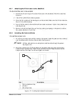
Страница 41: ... 4 Install the shifter bearing so the pin on the bearing engages the oblong hole in the rotate pulley 5 Lubricate the O ring with Parker O ring lubricant or equivalent and install it in the nozzle holder 6 Make sure the O ring is on the side of the nozzle holder opposite the slot in the swivel base Slide the nozzle holder into the swivel base Position the O ring properly to prevent it from being c...

Страница 42: ... module adjusting wrench supplied in the service kit in the gap The wrench is 1 8 inch thick and should fit snugly in the gap 6 Align the rotate and tilt mechanisms as shown in Figure 4 14 7 Tighten the rotate pulley clamp screw securely Slide the shifter bearing up and down the extension to make sure the entire tilt mechanism moves freely and does not bind Item Description Item Description 1 Micr...

Страница 43: ...y pushing and pulling on the piston rod where the cylinder attaches to the tilt fork 4 6 8 Installing the Solenoid Valve To install the solenoid valve 1 If you have previously removed the solenoid valve gasket place the gasket convex side up over the drilled ports in the top of the manifold See Figure 4 1 NOTE All three ports and two mounting holes must be visible through the gasket See Figure 4 1...

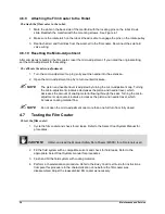
Страница 44: ...justed by turning the micro adjustment cap Turning the micro adjustment clockwise decreases the piston and needle travel which decreases the amount of coating material flowing through the seat Turning the micro adjustment cap counterclockwise increases the piston and needle travel which increases coating material flow NOTE Do not open the micro adjustment cap more than one full turn from fully clo...

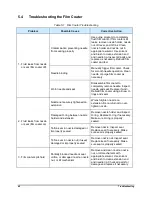
Страница 45: ...5 2 Safety First Operation of the SC 10X Series High Speed Film Coater involves air pressure electrical power mechanical devices and the use of hazardous materials It is essential that every person servicing or operating the film coater fully understands all hazards risks and safety precautions Refer to Section 2 Safety for additional information 5 3 Record Keeping The type of procedure performed ...

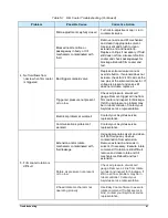
Страница 46: ... Replace if worn Rebuild film coater using all new O rings and seals 2 Fluid leaks from nozzle or seat film coater on Nozzle not securely tightened on extension Wrench tighten nozzle on extension Be careful not to over tighten nozzle Damaged O ring between nozzle holder and extension Remove nozzle holder and inspect O ring Replace O ring if necessary Make sure O ring is properly seated Teflon seal...

Страница 47: ...orkcell gauge Remove trigger air line from film coater and inspect for blockage If still no air pressure problem may be in robot controller Contact your Asymtek service representative Electrical problem at workcell Contact your Asymtek service representative Communications problem at workcell Contact your Asymtek service representative 5 Film coater rotation is difficult Extension and or rotate me...

Страница 48: ...eplace parts if necessary When rebuilding check that all fifth axis parts move freely Tilt air pressure not present or too low Check air pressure at workcell gauge Remove tilt cylinder air line and inspect for blockage If still no air flow problem may be in robot controller Contact your Asymtek service representative Communications problem at workcell Use Easy Coat software to execute tilt command...

Страница 49: ...f replaced parts names of technicians and other pertinent data should be recorded WARNING Some part replacement procedures involve the use and disposal of hazardous materials Always follow the material manufacturer MSDS facility requirements and local regulations for protection of personnel and disposal of materials 6 4 Parts Ordering Information 6 4 1 Placing Your Order Customers can order spare ...

Страница 50: ...isible after a failed part is removed from the coating applicator Inspect the area for signs of what may have caused the part to fail This may help prevent future part damage While removing parts that will be reinstalled visually inspect them for damage If found undamaged retain them for reinstallation Replace damaged parts and hardware as appropriate 6 6 Unpacking and Inspecting Replacement Parts...

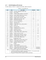
Страница 51: ...ated The number in the Quantity column is the quantity required per unit assembly or subassembly The code AR As Required is used if the part number is a bulk item ordered in quantities or if the quantity per assembly depends on the product version or model Letters in the Note column refer to notes at the end of each parts list Notes contain important information about usage and ordering Special at...

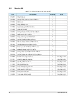
Страница 52: ...5 115052 Seal Hat Formed 2 A 16 195741 Body Upper SC 100 1 B 17 940119 O ring Thiokol 0 313 x 0 438 x 0 06 in 3 A 18 195742 Seal U cup 3 16 x 3 8 x 3 32 1 A C 19 983259 Washer Flat E 0 497 OD x 0 196 in 1 20 986115 Ring Retaining int 0 500 in basic 1 A 21 940146 O ring Thiokol 0 500 x 0 62 in 1 A 22 Body Module Lower 1 23 983059 Washer Flat E Teflon 0 500 x 0 19 in 1 A 24 941142 O ring Zalak 0 50 ...

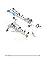
Страница 53: ...Illustrated Parts List 47 Figure 6 1 SC 104 Film Coater Exploded View 1 2 3 4 5 6 6 7 8 9 10 11 12 13 14 15 29 30 28 27 26 25 24 23 22 21 20 16 18 19 17 ...

Страница 54: ...ozzles 10 48 5208 Screw 1 4 20x1 2 soc flat 2 0 90 Rotate 11 198501 Pulley 3mm pitch 18 tooth 1 0 90 Rotate 12 48 3308 Screw 8 32 x 1 2 Sock Cap SS 4 0 90 Rotate 13 198505 Mount Rotary Cylinder 1 0 90 Rotate 14 145469 Manifold SC 10X 1 15 7203820 Ftg 1 8 tube 1 8npt 316ss 1 16 43 1150 80 Fitting Union 10 32 thd 1 8 tube 1 17 7206390 RTD Probe 1 8D 2 5 Long 1 For C 74X Series Dispensing Systems 17 ...

Страница 55: ...Illustrated Parts List 49 Figure 6 2 SC 104HS Exploded View 1 2 3 4 5 6 7 8 9 10 11 12 13 14 15 16 18 19 20 21 17 ...

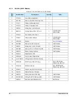
Страница 56: ...s On Line 1 4 125030 Base Swivel 5 axis On Line 1 5 125028 Lever Tilt 5 axis On Line 1 6 115375 Link Tilt 1 7 115056 Bearing Bronze 125X 188X 2 8 981550 Scr Pan 5 40X 312 STL NKL 2 9 7222129 Pulley Timing 24T 3MM HTD 1 10 7219263 Cylinder Rotate 270 Deg 2 11 49 43XX Screws 3 12 49 4002 Washer Flat M4 4 13 48 4035 Nut Hex 10 32 SST 2 14 7221256 Fork Tilt Film Coater 1 15 7221253 Cyl 9 16 D 280 L Ex...

Страница 57: ...Illustrated Parts List 51 Figure 6 3 SC 105HS Exploded View 0 360 1 2 3 4 5 8 6 7 9 12 10 11 13 14 15 16 17 ...

Страница 58: ...Connector Male 1 8 x 10 32 NPT 3 13 115388 Fork Tilt 1 14 984120 Nut Hex Machined 10 32 5 15 981148 Screw Fillister Head 10 32 x 1 25 in 1 16 115380 Stop Cylinder Adjustment 1 17 115379 Cylinder 9 16 in Bore 1 2 in Stroke 1 18 115381 Block Clamping Cylinder 1 18 145469 Manifold SC 105 High Speed 1 20 145460 Valve Micro Solenoid 4 way with Connector 1 21 971235 Connector Male 1 4 x 1 8 NPT 2 22 981...

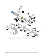
Страница 59: ...Illustrated Parts List 53 Figure 6 4 SC 105HS Film Coater Century C 74X Systems Exploded View 1 2 3 5 4 7 6 8 9 10 11 12 13 14 15 17 18 19 12 20 12 21 22 11 23 24 25 26 29 28 27 16 ...

Страница 60: ...1 983059 Washer flat E Teflon 0 500 x 0 19 in 1 941142 O ring Zalak 0 50 x 0 63 x 0 06 in 1 981550 Screw pan head 5 40 x 0 312 in ss 2 115056 Bearing bronze 0 125 x 0 188 in 1 945015 O ring Chemraz 0 250 x 0 375 x 0 062 in 1 940105 O ring Teflon 190 0 250 x 0 375 x 0 062 in 1 115059 Insertion tool ring and seal 1 See Figure 6 5 901911 Wrench adjusting module 2 See Figure 6 5 48 8006 Hex Key Wrench...

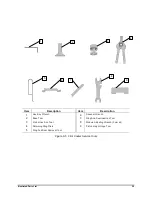
Страница 61: ...x Key Wrench 6 Spanner Wrench 2 Base Tool 7 Ring And Seal Insertion Tool 3 Piston Insertion Tool 8 Module Adjusting Wrench 2 per kit 4 Retaining Ring Pliers 9 Piston Height Gage Tool 5 Ring And Seal Removal Tool Figure 6 5 Film Coater Service Tools 1 2 3 4 5 6 7 8 9 ...

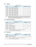
Страница 62: ...d enamel placed 10 inches from the nozzle Use the values for comparative purposes only they do not correlate directly to the flow or pattern obtained with specific conformal coatings 6 10 Nozzle Cleaning Kit Table 6 7 Nozzle Cleaning Kit Part Description Quantity Note 901934 Kit nozzle cleaning 1 901916 S Vise pin 1 901935 S Probe vial 0 003 in 1 A 901922 S Probe vial 0 007 in 1 B 901923 S Probe v...

Страница 63: ...arts List 57 6 12 Nozzle Brush Table 6 9 Nozzle Brush Part Description Quantity Note 901905 Brush nozzle 1 6 13 Nozzle Seal Tool Table 6 10 Nozzle Seal Tool Part Description Quantity Note 326382 Seal expander tool 1 ...

Страница 64: ...P N 108384 Revision L 2010 Asymtek Headquarters 2762 Loker Avenue West Carlsbad CA 92010 6603 USA Tel 760 431 1919 ...

Отзывы: