


Setup Pages and Descriptions
64
NXD-700i & NXT-CA7 7” Modero Touch Panels
Making the most of the Light bargraph
By setting a certain minimum or maximum amount of light to be received by the device, the Light bargraph
may be used to trigger particular commands in NetLinx. The red line on the Light Sensor bargraph is the
threshold level. It is used to determine the level of light at which to activate the Light Sensor Channel. The
channel is activated when the light level is below the threshold and deactivated when above the threshold. For
more information, refer to the
Programming
section on page 71.
Making the most of the Motion Sensor feature
The motion sensor works by detecting the heat of objects passing by the front of the touch panel. Because of
this, the sensor works best when detecting lateral movement, such as when a person walks in front of the touch
panel from left to right. This appears in the Motion Sensor bar based on the signal strength: a hand waved
directly in front of the motion sensor is going to produce a stronger signal than a person walking by at the outer
range of the sensor. The sensitivity may be modified by environmental conditions, such as increased body heat
or outside heat sources such as sunbeams or heater vents. To set the Motion Sensor to best effect:
1.
Ascertain the intended sensitivity of the Motion Sensor. For instance, check to see if commands are to be
initiated by someone walking past the touch panel, if someone enters the room at the edge of the touch
panel’s range, or if someone specifically reaches for the panel’s face.
2.
Open the
Sensor Settings
page (FIG. 62) from the
Protected Setup
menu section.
3.
Watch the movement of the Motion Sensor bar while holding perfectly still. This allows tracking of other
factors that might affect the Motion Sensor, such as air conditioner vents or moving curtains.
4.
Copy the movement intended to set off the Sensor while watching the Motion Sensor bar, such as walking
past the device. In particular, watch for the spikes in the bar where the sensor picked up the most
movement.
5.
Set the Motion Sensor bar to the desired sensitivity, making sure that it is located below the spikes
previously noted. If the bar is set above the level of the spikes, the Motion Sensor may never be set off by
that level of motion.
6.
Repeat the movement and check to see if the movement exceeds the bar setting. Adjust the bar as
necessary to set the desired sensitivity.
SIP Settings Page
The options on the SIP Settings page (FIG. 63) enable you to establish network settings for using your touch
panel as an IP phone. With a CSG SIP Communications Gateway (
FG2182-01, -02, -03
), you can use your
touch panel to make and receive local, long distance, and international phone calls, and have access to phone
features like call waiting, caller ID, call forwarding, call queuing, and voice mail.
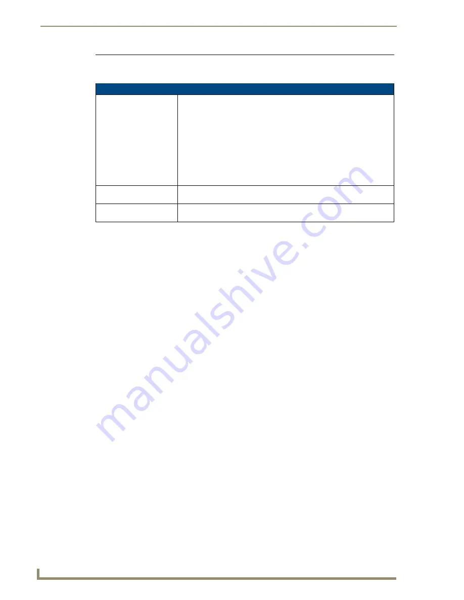
Sensor Settings (Cont.)
Wake On Motion:
The Wake Panel Sensitivity relates to the sensitivity of the motion sensor to
detect motion and wake the panel accordingly.
• Toggle the
Enable
/
Enabled
button to either active/inactive this feature:
-
Enable
- activates this feature. Activating this feature reactivates the panel
from a panel timeout (sleep) mode.
-
Enabled
- (
illuminated when selected
) deactivates this feature and makes
the panel use the specified Display Timeout value set on the Setup Page.
• Use the
Wake Panel
UP/DN buttons to alter the sensitivity value.
- Range = 0 - 100.
• The horizontal WAKE PANEL SENSITIVITY bargraph indicates the current
motion sensitivity value associated with waking the panel from a timeout.
IR Receive Selection:
Press either of the two buttons to enable or disable 38 KHz or 455 KHz IR
signals to be received by the panel.
Motion:
The Motion bargraph displays a vertical bargraph indicating the current value of
the motion detected by the on-board motion detector.
Содержание NXD-700i
Страница 4: ......
Страница 12: ...viii NXD 700i NXT CA7 7 Modero Touch Panels Table of Contents...
Страница 30: ...NXT CA7 Installation 18 NXD 700i NXT CA7 7 Modero Touch Panels FIG 19 RJ 45 wiring diagram...
Страница 52: ...Configuring Communication 40 NXD 700i NXT CA7 7 Modero Touch Panels...
Страница 138: ...Programming 126 NXD 700i NXT CA7 7 Modero Touch Panels...
Страница 148: ...Appendix A Text Formatting Codes 136 NXD 700i NXT CA7 7 Modero Touch Panels...
Страница 151: ...Appendix B Complex Script Support 139 NXD 700i NXT CA7 7 Modero Touch Panels...


