


Publication 1763-RM001B-EN-P - April 2007
Communications Instructions
347
The Message Element
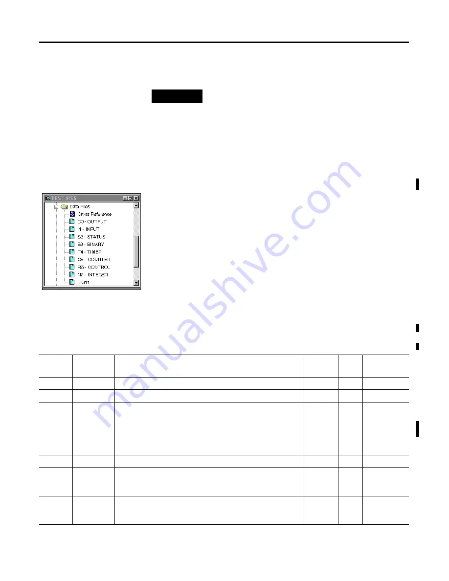
The MSG instruction built into the controller uses a MG data file to
process the message instruction. The MG data file, shown at left, is
accessed using the MG prefix. Each message instruction utilizes an
element within a MG data file. For example, MG11:0 is the first element in
message data file 11.
Message File Sub-Elements
Each MSG instruction must use a unique Element in a MSG File. The MSG
element for each MSG instruction holds all of the parameters and status
information for that particular MSG instruction.
Each MSG File Element consists of Sub-Elements 0 through 24 as shown
in the following table.
TIP
How quickly the message is actually sent to the
destination device depends on a number of issues,
including the selected channel’s communication
protocol, the baud rate of the communications port, the
number of retries needed (if any), and the destination
device's readiness to receive the message.
Message File Elements
Sub-
Element
Name
Description
Paramet
er
Size
User Program
Access
(2)
0 to 1
Reserved
Word
read only
2
Messaging Type: 0 (for PCCC), 1 (for CIP), 2 (for Modbus Master)
Word
read only
3
for PCCC Messaging: bits 07-00 (CMD code), bits 15-08 (FNC code)
for CIP: bits 07-00 (Service Code), bits 15-08 (Supplemental Object
Path Data Count)
for Modbus Master: bits 07-00 (Function Code), bits 15-08 (reserved)
derived
Word
read only
4
Internal Physical Address
Word
read only
5
MG11:0.RBL
PCCC: Remote Bridge Link ID
Modbus Master: not used
Y
Word
read only
6
MG11:0.LBN
PCCC: Local Bridge Node Address
Modbus Master: not used
Y
Word
read only
efesotomasyon.com - Allen Bradley,Rockwell,plc,servo,drive


