


BRIDGE NDI 3G Conversion Gateway Appliance v1.0 41 www.aja.com
If BRIDGE NDI 3G is already up and running and you are ready to re-cable as
necessary, then the Presets Tab is a fast way to choose between numerous
system-wide configurations. Used in conjunction with the Cabling Tab, this can
make for an efficient method to rapidly re-setup a system for a new task.
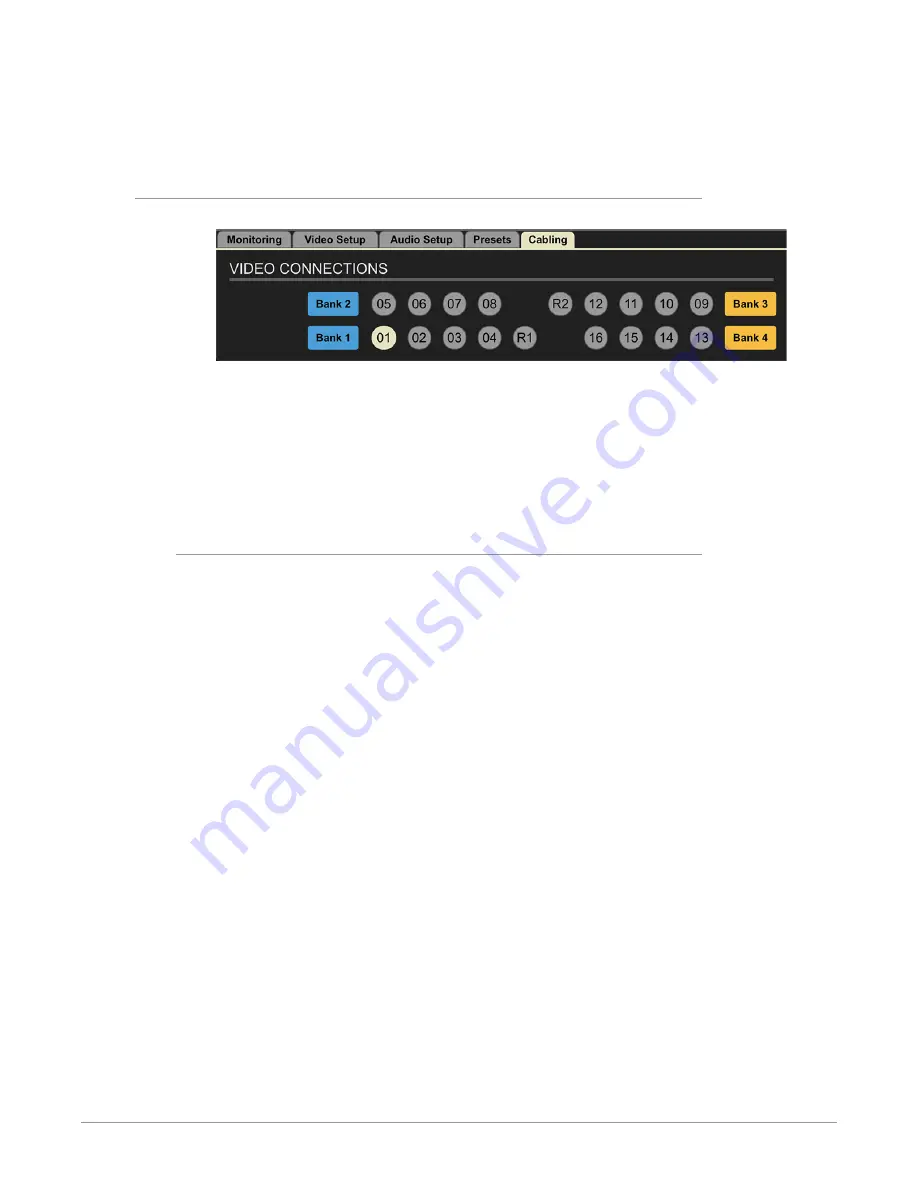
Control Bar – Cabling Tab
Figure 41. Cabling Tab
Within the Cabling Tab Screen, the BNC connector for the currently selected
Video Tile will be highlighted. This is for ease of cabling setup, troubleshooting,
reconfiguring, and to make it easy to know which cabling connection is relevant
to your currently selected Video Tile. This is especially helpful when you need to
make directional changes that may impact your cabling.
Particularly when making directional changes (SDI to NDI or NDI to SDI), you will
need to take the cabling into account to keep everything working smoothly.
Cabling Considerations and Changing Directions
Because BRIDGE NDI 3G is a gateway device, it is not expected that you will need
to change your cabling connections very frequently. However, when cabling
changes are required the diagram in the Cabling Tab will help you quickly identify
NOTE: While it is really easy to change directions (NDI to SDI or SDI to NDI) on the
interface, please keep in mind that it may impact cabling connections and other
configurations.
Cabling: shows a map that corresponds to how the connectors are arranged on
the back of the box. Very helpful visual reference guide. Any channels that are
currently selected are indicated by dark blue, making it clear which connectors
correspond to actions you are taking at the time.
If you have grouped channels into a 4K group, and you select that 4K group on
the I/O Screen, it will light up that whole bank on the Cabling Tab.
For example, if you select V+K pair (using Ch 1 and Ch 2), connectors 01 and 02 are
highlighted in Cabling Tab.
If you select a 4K Group in Bank 2, the Cabling Tab shows that Ch 05, 06, 07, 08 are
highlighted.
Audio monitoring controls are reflected here also.


