


In
st
alla
tio
n
Chillers
DeltaChill™ Air Cooled and FreeCool
40
Chiller Technical Manual 7267818 V1.13.0_01_2018
Installation Data
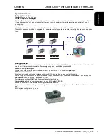
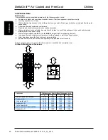
Positioning
The installation position should be selected with the following points in mind:
●
Position on a stable and even base, levelled to ensure that the compressor operates correctly
●
Levelling should be to +/- 5mm.
● Where vibration transmission to the building structure is possible, fit spring anti-vibration mounts and flexible water
connections.
● Observe airflow and maintenance clearance.
●
Pipework and electrical connections are readily accessible.
●
Where multiple units are installed, due care should be taken to avoid the discharge air from each unit adversely
affecting other units in the vicinity.
●
Within a side enclosed installation, the fan
MUST
be higher than the enclosing structure.
● Increase airflow and maintenance clearances for side-enclosed or multiple unit applications.
●
Allow free space above the fans to prevent air recirculation.
●
Ensure that there is a safe access and operating area provided for unit controls.
Prior to connecting services, ensure that the equipment is installed and completely level.
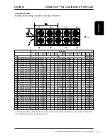
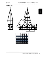
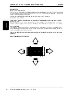
Airflow & Maintenance Clearances
A
A
B
C
D
Application
Distance from Overall Base Dimension (mm)
A
B
C
D
Free of walls and overhang
1300
1300
1300
1300
Enclosed to A
2600
1300
1300
1300
Unit parallel with A
2600
1300
1300
1300
Enclosed to B
1300
2600
1300
1300
Unit in line with B
1300
1300
1300
1300
Unit in line with C Controls End
1300
1300
2600
1300
Enclosed to C
1300
1300
2600
1300
Installation Data
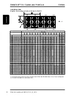
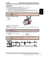
Anti Vibration Mounting (Optional)
Spring Type
Each mount is coloured to indicate the different loads, refer to instructions supplied for
correct allocation.
Dimensions
A(1)
B
C
D
E
F
162
130
225
186
20
16
(1)
Unloaded dimension
Components
1
Locating Screw
2
Retaining Nut & Washer
3
Levelling Screw
4
Levelling Lock Nut
5
Retaining Studs
6a
Upper Retaining Nuts
6b
Lower Retaining nuts
7
Spring assembly
8
Pressure Plate
9
Top Plate
10
Bolting-down holes
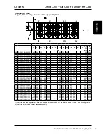
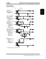
Installation
1. Locate and secure mount using bolting down holes (10) in base plate.
2. Ensure mounts are located in line with the unit base.
3.
If applicable, remove compressor enclosure covers to allow access to mount fi xing holes
in the unit base.
4. Lock the upper retaining nuts (6a) to the underside of the top plate (9) before a load is
applied.
5. Slacken levelling lock nut (4). (the levelling screw will not move if this is not slackened)
6. Remove retaining nut and washer (2), lower the unit onto the mounts and replace retaining nut and washer.
Beginning with the mount with the largest defl ection adjust the height of each mount using the levelling screw (3).
2
1
6a
5
6b
10
9
8
7
3 4
B
A
C
D
E
F
E
Mountings must be adjusted incrementally in turn.
Do not fully adjust 1 mount at a time as this may overload and damage springs.
When all mounts are level, lock each into place using the levelling lock nut (4)
Lock all retaining nuts (6a and 6b) to the extreme ends of the retaining studs (5)
Do not connect any services until all anti vibration mounts have been fully adjusted.
CAUTION
Содержание DeltaChill
Страница 1: ...Technical Manual DeltaChill Air Cooled DeltaChill Free Cooling Chiller 500kW 1000kW ...
Страница 300: ...Chillers Introduction DeltaChill Air Cooled and FreeCool 300 Chiller Technical Manual 7267818 V1 13 0_01_2018 Technical ...
Страница 301: ...Chillers DeltaChill Air Cooled and FreeCool Introduction 301 Chiller Technical Manual 7267818 V1 13 0_01_2018 Technical ...