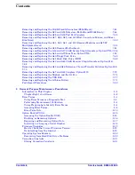
Contents
Service Guide E8364-90026
Contents-5
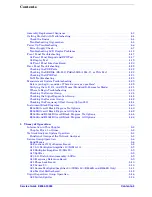
Bottom Assemblies, Options UNL/014/016 and UNL/014/016/080 . . . . . . . . . . . . . . . . . .6-40
Bottom Semi-Rigid Cables, Options UNL/014/016 and UNL/014/016/080 . . . . . . . . . . . .6-42
Bottom Assemblies, Options 014/080/081 . . . . . . . . . . . . . . . . . . . . . . . . . . . . . . . . . . . . . .6-44
Bottom Semi-Rigid Cables, Options 014/080/081 . . . . . . . . . . . . . . . . . . . . . . . . . . . . . . . .6-46
Bottom Assemblies, Options UNL/014/080/081. . . . . . . . . . . . . . . . . . . . . . . . . . . . . . . . . .6-48
Bottom Semi-Rigid Cables, Options UNL/014/080/081. . . . . . . . . . . . . . . . . . . . . . . . . . . .6-50
Bottom Assemblies, Options UNL/014/080/081/H11. . . . . . . . . . . . . . . . . . . . . . . . . . . . . .6-52
Bottom Semi-Rigid Cables, Options UNL/014/080/081/H11. . . . . . . . . . . . . . . . . . . . . . . .6-54
Bottom Assemblies, Options UNL/014/016/080/081 . . . . . . . . . . . . . . . . . . . . . . . . . . . . . .6-56
Bottom Semi-Rigid Cables, Options UNL/014/016/080/081 . . . . . . . . . . . . . . . . . . . . . . . .6-58
Bottom Assemblies, Options UNL/014/016/080/081/H11 . . . . . . . . . . . . . . . . . . . . . . . . . .6-60
Bottom Semi-Rigid Cables, Options UNL/014/016/080/081/H11 . . . . . . . . . . . . . . . . . . . .6-62
Bottom Flexible Cables, All Options . . . . . . . . . . . . . . . . . . . . . . . . . . . . . . . . . . . . . . . . . .6-64
Bottom Ribbon Cables and Wrapped-Wire, All Options . . . . . . . . . . . . . . . . . . . . . . . . . . .6-66
Top Hardware, All Options . . . . . . . . . . . . . . . . . . . . . . . . . . . . . . . . . . . . . . . . . . . . . . . . . .6-68
Bottom Hardware, All Options. . . . . . . . . . . . . . . . . . . . . . . . . . . . . . . . . . . . . . . . . . . . . . .6-70
Internal Hardware and Parts, All Options . . . . . . . . . . . . . . . . . . . . . . . . . . . . . . . . . . . . .6-72
External Hardware and Parts, All Options . . . . . . . . . . . . . . . . . . . . . . . . . . . . . . . . . . . . .6-74
Rear Panel Assembly, All Options . . . . . . . . . . . . . . . . . . . . . . . . . . . . . . . . . . . . . . . . . . . .6-76
Hard Disk Drive Assembly . . . . . . . . . . . . . . . . . . . . . . . . . . . . . . . . . . . . . . . . . . . . . . . . . .6-78
Miscellaneous Part Numbers . . . . . . . . . . . . . . . . . . . . . . . . . . . . . . . . . . . . . . . . . . . . . . . .6-80
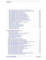
Repair and Replacement Procedures
Removal and Replacement Procedures . . . . . . . . . . . . . . . . . . . . . . . . . . . . . . . . . . . . . . . . . . .7-4
Removing the Covers . . . . . . . . . . . . . . . . . . . . . . . . . . . . . . . . . . . . . . . . . . . . . . . . . . . . . . . . .7-6
Raising and Removing the Receiver Deck . . . . . . . . . . . . . . . . . . . . . . . . . . . . . . . . . . . . . . . .7-8
Removing and Replacing the Front Panel Assembly . . . . . . . . . . . . . . . . . . . . . . . . . . . . . . .7-10
Removing and Replacing Front Panel Subassemblies . . . . . . . . . . . . . . . . . . . . . . . . . . . . . .7-12
Removing and Replacing the Display Inverter Board and the Display Lamp . . . . . . . . . . .7-14
Removing and Replacing the A4 Power Supply Assembly. . . . . . . . . . . . . . . . . . . . . . . . . . .7-16
Removing and Replacing the A6, A8, A9, and A10 Boards . . . . . . . . . . . . . . . . . . . . . . . . . .7-18
Removing and Replacing the A11 Phase Lock Board. . . . . . . . . . . . . . . . . . . . . . . . . . . . . . .7-20
Removing and Replacing the A12 Source 20 . . . . . . . . . . . . . . . . . . . . . . . . . . . . . . . . . . . . .7-22
Removing and Replacing the A13 Frequency Offset Receiver Assembly . . . . . . . . . . . . . . .7-24
Removing and Replacing the A14 System Motherboard . . . . . . . . . . . . . . . . . . . . . . . . . . . .7-26
Removing and Replacing the A15 CPU Board . . . . . . . . . . . . . . . . . . . . . . . . . . . . . . . . . . . .7-28
Removing and Replacing the A16 Test Set Motherboard. . . . . . . . . . . . . . . . . . . . . . . . . . . .7-30
Removing and Replacing the A17 LOMA 10 . . . . . . . . . . . . . . . . . . . . . . . . . . . . . . . . . . . . .7-32
Removing and Replacing the A18 MA 20 . . . . . . . . . . . . . . . . . . . . . . . . . . . . . . . . . . . . . . . .7-34
Removing and Replacing the A19 Splitter . . . . . . . . . . . . . . . . . . . . . . . . . . . . . . . . . . . . . . .7-36
Removing and Replacing the A20 LODA . . . . . . . . . . . . . . . . . . . . . . . . . . . . . . . . . . . . . . . .7-38
Removing and Replacing the A21 SOMA 50 (E8363B and E8364B Only) . . . . . . . . . . . . .7-40
Removing and Replacing the A22 Switch Splitter . . . . . . . . . . . . . . . . . . . . . . . . . . . . . . . . .7-42
Содержание E8362B
Страница 11: ...Service Guide E8364 90026 1 1 1 Safety and Regulatory Information ...
Страница 19: ...Service Guide E8364 90026 2 1 2 General Product Information ...
Страница 33: ...Service Guide E8364 90026 3 1 3 Tests and Adjustments ...
Страница 83: ...Service Guide E8364 90026 4 1 4 Troubleshooting ...
Страница 151: ...Service Guide E8364 90026 5 1 5 Theory of Operation ...
Страница 185: ...Service Guide E8364 90026 6 1 6 Replaceable Parts ...
Страница 269: ...Service Guide E8364 90026 7 1 7 Repair and Replacement Procedures ...
Страница 351: ...Service Guide E8364 90026 8 1 8 General Purpose Maintenance Procedures ...


