


7-18
Service Guide E8364-90026
Repair and Replacement Procedures
PNA Series Microwave Network Analyzers
Removing and Replacing the A6, A8, A9, and A10 Boards
E8362B, E8363B, E8364B
Removing and Replacing the A6, A8, A9, and A10 Boards
Tools Required
• T-10 TORX driver (set to 9 in-lb)
• T-20 TORX driver (set to 21 in-lb)
• ESD grounding wrist strap
Removal Procedure
Refer to
for this procedure.
1. Disconnect the power cord.
2. Remove the outer and inner covers. Refer to
“Removing the Covers” on page 7-6
.
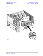
3. With a T-10 TORX driver, remove the two brackets that secure cables to the top of the
midweb.
4. Identify the board you want to remove and disconnect any cables that are attached to it.
5. Lift the two extractors (item
①
), located at each end of the board.
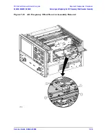
NOTE
Before removing the board completely, check the bottom of the board for any
attached cables.
6. While holding on to the extractors, slide the board out of the slot and remove it from the
analyzer.
Replacement Procedure
1. Reverse the order of the removal procedure.
2. Perform the post-repair adjustments, verifications, and performance tests that pertain
to this removal procedure. Refer to
Содержание E8362B
Страница 11: ...Service Guide E8364 90026 1 1 1 Safety and Regulatory Information ...
Страница 19: ...Service Guide E8364 90026 2 1 2 General Product Information ...
Страница 33: ...Service Guide E8364 90026 3 1 3 Tests and Adjustments ...
Страница 83: ...Service Guide E8364 90026 4 1 4 Troubleshooting ...
Страница 151: ...Service Guide E8364 90026 5 1 5 Theory of Operation ...
Страница 185: ...Service Guide E8364 90026 6 1 6 Replaceable Parts ...
Страница 269: ...Service Guide E8364 90026 7 1 7 Repair and Replacement Procedures ...
Страница 351: ...Service Guide E8364 90026 8 1 8 General Purpose Maintenance Procedures ...


