


7-62
Service Guide E8364-90026
Repair and Replacement Procedures
PNA Series Microwave Network Analyzers
Removing and Replacing the A41 Hard Disk Drive (HDD)
E8362B, E8363B, E8364B
Removing and Replacing the A41 Hard Disk Drive (HDD)
Certain unique files exist on the hard disk drive that are necessary for proper operation of
your analyzer. These files must be copied to another location to allow them to be installed
onto the new HDD after it has been installed.
If you are replacing the HDD, not just removing the hard disk drive assembly (HDDA) to
allow access to other assemblies, the following procedure must be performed first.
If you are not replacing the actual HDD, proceed to
on this page.
Copy Unique Files from the Hard Disk
1. Insert a writable floppy disk into the floppy disk drive, or insert a USB flash memory
drive into a USB port.
2. Open
Windows
Explorer
.
3. Navigate to
C:\Program Files\Agilent\Network Analyzer
.
4. Copy each of the following files from the hard disk drive to the floppy disk or the USB
drive:
•
gen.lic
• user_calkitfile
• All files prefixed with
mxcalfile_
.
• Any personal user files that you wish to preserve.
5. Remove the storage device containing the backup files: either the floppy disk from the
analyzer’s disk drive, or the USB drive from the USB port.
6. Exit
Windows Explorer
.
Tools Required
• T-10 TORX driver (set to 7 in-lb; for hard disk drive replacement)
• T-10 TORX driver (set to 9 in-lb; for all other T-10 applications)
• ESD grounding wrist strap
Removal Procedure
1. Disconnect the analyzer power cord.
for the remainder of this procedure.
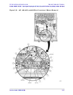
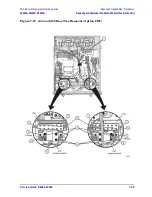
2. With a T-10 TORX driver, loosen the four HDDA mounting screws (item
①
) on the rear
panel.
3. Remove the HDDA from the analyzer by pulling on the finger grip (item
②
). The HDDA
interconnects with a connector inside the analyzer rear panel so moderate force may be
necessary to disengage this connector.
Содержание E8362B
Страница 11: ...Service Guide E8364 90026 1 1 1 Safety and Regulatory Information ...
Страница 19: ...Service Guide E8364 90026 2 1 2 General Product Information ...
Страница 33: ...Service Guide E8364 90026 3 1 3 Tests and Adjustments ...
Страница 83: ...Service Guide E8364 90026 4 1 4 Troubleshooting ...
Страница 151: ...Service Guide E8364 90026 5 1 5 Theory of Operation ...
Страница 185: ...Service Guide E8364 90026 6 1 6 Replaceable Parts ...
Страница 269: ...Service Guide E8364 90026 7 1 7 Repair and Replacement Procedures ...
Страница 351: ...Service Guide E8364 90026 8 1 8 General Purpose Maintenance Procedures ...


