


Service Guide E8364-90026
3-35
PNA Series Microwave Network Analyzers
Tests and Adjustments
E8362B, E8363B, E8364B
Performance Tests (Agilent N7840A Software Package)
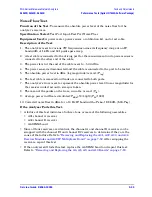
Noise Floor Test
Function of the Test:
To measure the absolute power level of the noise floor for the
analyzer’s receivers.
Specification Tested:
Test Port Input–Test Port Noise Floor
Equipment Used:
A power meter, power sensor, a calibration kit, and a test cable.
Description of the Test:
1. The analyzer is set to various CW frequencies across its frequency range at an IF
bandwidth of 1 kHz and 801 points per sweep.
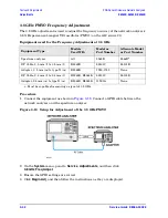
2. A test cable is connected to the driving port for the measurement and a power sensor is
connected to the other end of the cable.
3. The power level at the end of the cable is set to
−
5.00 dBm.
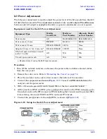
4. The power sensor is disconnected and the cable is connected to the port to be tested.
5. The absolute power level in dBm (log magnitude) is read: (
P
log
).
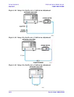
6. The test cable is removed and loads are connected to both ports.
7. The analyzer’s trace is set to represent the absolute power level (linear magnitude) for
the receiver under test and a sweep is taken.
8. The mean of the points on the trace, in watts, is read: (
P
lin
).
9. Average power in dBm is calculated:
P
dBm
=
10
∗
Log10(P
lin
∗
1000)
.
10. Corrected noise floor in dBm for a 10 Hz IF bandwidth =
P
dBm
−
19.96 dB
−
(5.00-P
log
)
.
If the Analyzer Fails this Test:
• A failure of this test indicates a failure of one or more of the following assemblies.
• A31 channel A receiver
• A34 channel B receiver
• A6 SPAM board
• Since all four receivers are identical, the channel A and channel B receivers can be
swapped with the channel R1 and channel R2 receivers to determine if they are the
cause of the failure. Refer to
“Removing and Replacing the A31, A32, A33, and A34
Receiver Modules and A49 IF Multiplexer Board” on page 7-52
. After swapping the
receivers, repeat this test.
• If the analyzer still fails this test, replace the A6 SPAM board and repeat this test.
Refer to
“Removing and Replacing the A6, A8, A9, and A10 Boards” on page 7-18
.
Содержание E8362B
Страница 11: ...Service Guide E8364 90026 1 1 1 Safety and Regulatory Information ...
Страница 19: ...Service Guide E8364 90026 2 1 2 General Product Information ...
Страница 33: ...Service Guide E8364 90026 3 1 3 Tests and Adjustments ...
Страница 83: ...Service Guide E8364 90026 4 1 4 Troubleshooting ...
Страница 151: ...Service Guide E8364 90026 5 1 5 Theory of Operation ...
Страница 185: ...Service Guide E8364 90026 6 1 6 Replaceable Parts ...
Страница 269: ...Service Guide E8364 90026 7 1 7 Repair and Replacement Procedures ...
Страница 351: ...Service Guide E8364 90026 8 1 8 General Purpose Maintenance Procedures ...


