


Service Guide E8364-90026
3-23
PNA Series Microwave Network Analyzers
Tests and Adjustments
E8362B, E8363B, E8364B
System Verification
Performing System Verification
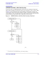
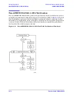
The following verification procedure is automated by the analyzer firmware. For each
verification device, the analyzer reads a file from the verification disk and sequentially
measures the magnitude and phase for all four S-parameters.
IMPORTANT
For system verification to perform correctly, it is NECESSARY that the
verification devices be measured with their female connectors connected to
Port 1 and their male connectors connected to Port 2.
NOTE
The following procedure, and the connection prompts given, assumes only one
female-to-female cable connected to Port 2. However, this procedure can also
be performed with the addition of a female-to-male cable connected to Port 1.
NOTE
Although the performance for all four S-parameters are measured, the S
11
and S
22
phase uncertainties for the attenuators and airlines are less
important for verifying system performance. Therefore, the limit lines will
not appear on the printout.
Equipment Supported by the System Verification Procedure
Cable Substitution
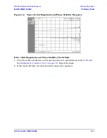
The test port cables specified for the network analyzer system have been characterized for
connector repeatability, magnitude and phase stability with flexing, return loss, insertion
loss, and aging rate. Since test port cable performance is a significant contributor to the
system performance, cables of lower performance will increase the uncertainty of your
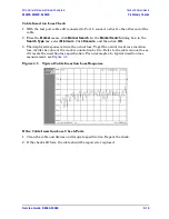
measurement. Refer to the plots in the cable tests (earlier in this chapter) that show the
performance of good cables. It is highly recommended that the test port cables to be
regularly tested.
If the system verification is performed with a non-Agilent cable, ensure that the cable
meets or exceeds the specifications for the RF cable specified in the above table,
“Equipment Supported by the System Verification Procedure.”
Refer to the cable’s user’s
guide for specifications.
Kit Substitution
Non-Agilent calibration kits and verification kits are not recommended nor supported.
Equipment Type
Type-N
3.5 mm
2.4 mm
E8362B
E8362/3/4B
E8363/4B
Calibration kit
85054B/D
85052B/D
85056A/D
Verification kit
85055A
85053B
85057B
Cables
85131C/E (with 85130C
3.5 mm to Type-N adapter
set)
E8362B: 85131C/E
E8363/4B: 85133C/E (with
85130F 2.4 mm to 3.5 mm
adapter set)
85133C/E
Содержание E8362B
Страница 11: ...Service Guide E8364 90026 1 1 1 Safety and Regulatory Information ...
Страница 19: ...Service Guide E8364 90026 2 1 2 General Product Information ...
Страница 33: ...Service Guide E8364 90026 3 1 3 Tests and Adjustments ...
Страница 83: ...Service Guide E8364 90026 4 1 4 Troubleshooting ...
Страница 151: ...Service Guide E8364 90026 5 1 5 Theory of Operation ...
Страница 185: ...Service Guide E8364 90026 6 1 6 Replaceable Parts ...
Страница 269: ...Service Guide E8364 90026 7 1 7 Repair and Replacement Procedures ...
Страница 351: ...Service Guide E8364 90026 8 1 8 General Purpose Maintenance Procedures ...


