4-42
Service Guide E8364-90026
Troubleshooting
PNA Series Microwave Network Analyzers
Measurement System Troubleshooting
E8362B, E8363B, E8364B
A phase lock problem is due to either:
• faulty RF signal generation (caused by the A12 source 20, A21 SOMA 50, A23 and A24
SOMA 70)
• faulty LO signal generation (caused by the A8, A10, A11, A17 or A18 board)
RF Signal Troubleshooting
To isolate a broadband RF signal generation failure, check the test port output power:
1. Connect a power meter and power sensor to Port 1 of the analyzer.
2. On the analyzer, press
Preset
, set the
Center Frequency
to
2 GHz
, and the
Frequency
Span
to
0 Hz
. Note the power reading displayed on the power meter. The output power,
as indicated on the power meter, should be approximately
−
12 dBm ±5 dB for an
analyzer with no hardware options or -17 dBm ±5 dB for an analyzer with options.
NOTE
In the unlocked state, the analyzer will “search” for the reference signal.
3. Connect the power sensor to Port 2 and set trace to measure S
22
. Note the power
reading displayed on the power meter. The power meter reading should be the same as
was measured at Port 1.
• If the power level is low at both test ports the problem is either the A12 source 20 or the
A21 SOMA 50. Continue with
“Checking the A12 Output, All Bands”
.
• If the output power is high at both test ports the problem is LO signal related. Continue
with
.
LO Signal Troubleshooting
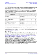
To isolate a broadband LO signal, refer to the data obtained from the
:
• If the data obtained for the A10 frequency reference board is out of tolerance, confirm
the failure with the following checks for the A10 board starting on
• If the data obtained for the A10 frequency reference board is correct but the data for the
A8 fractional-N synthesizer board is out of tolerance, confirm the failure with the
following checks for the A8 board on starting on
.
• If the data obtained for the A8 fractional-N synthesizer board is correct—and the RF
has been checked—but there is still a phase lock problem, confirm the failure with the
following checks for the A17, A18, and A20 boards starting on
.
Checking the A12 Output, All Bands
1. Disconnect W1 from A12.
2. Connect a cable to A12 and measure the output power. A power level of a
−1
7 dBm
±
5
dB indicates the A12 assembly is functioning normally.
3. If the output power of A12 is at or below the minimum power level, replace the A12
source 20 assembly.
4. If the output power is normal, reconnect cable W1 to A12.
Содержание E8362B
Страница 11: ...Service Guide E8364 90026 1 1 1 Safety and Regulatory Information ...
Страница 19: ...Service Guide E8364 90026 2 1 2 General Product Information ...
Страница 33: ...Service Guide E8364 90026 3 1 3 Tests and Adjustments ...
Страница 83: ...Service Guide E8364 90026 4 1 4 Troubleshooting ...
Страница 151: ...Service Guide E8364 90026 5 1 5 Theory of Operation ...
Страница 185: ...Service Guide E8364 90026 6 1 6 Replaceable Parts ...
Страница 269: ...Service Guide E8364 90026 7 1 7 Repair and Replacement Procedures ...
Страница 351: ...Service Guide E8364 90026 8 1 8 General Purpose Maintenance Procedures ...

