


Service Guide E8364-90026
4-35
PNA Series Microwave Network Analyzers
Troubleshooting
E8362B, E8363B, E8364B
Measurement System Troubleshooting
Checking the Source Group
Serial Bus Test
Before performing tests on specific assemblies in the source group, it is recommended that
you perform the serial bus test. This may help to isolate the failure to a specific assembly.
Through the front panel, the serial bus test allows you to check signal and voltage levels at
32 points (nodes) distributed across four of the printed circuit board assemblies in the
analyzer. With this test you can isolate problem board assemblies in the analyzer. The
board assemblies tested and their associated node numbers are as follows:
NOTE
This test is written for a PNA series network analyzer as it was originally
shipped from the factory. Due to changes in board production, this test may
not show accurate pass/fail results if the A8, A10, A11, A12, or A16 board
have been replaced with newer board assemblies.
Descriptions of each board assembly and node is included in this section. Location of the
nodes is indicated with a
♦
symbol on the block diagrams located at the end of this chapter.
Performing the Serial Bus Test
First, this test sequentially checks all 48 nodes at 45 MHz. Next, the test checks all nodes
that change values with frequency, at 49 different frequency points. For each node,
measured values are copied to an ASCII text file in the service directory on the hard disk
drive. Any measured values that exceed the tolerances are highlighted in the application
and the data file.
To run the serial bus test:
• On the
System
menu, point to
Service,
and then click
Serial Bus Test
.
• The dialog box in
is displayed. Click
Begin
to start the test.
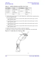
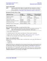
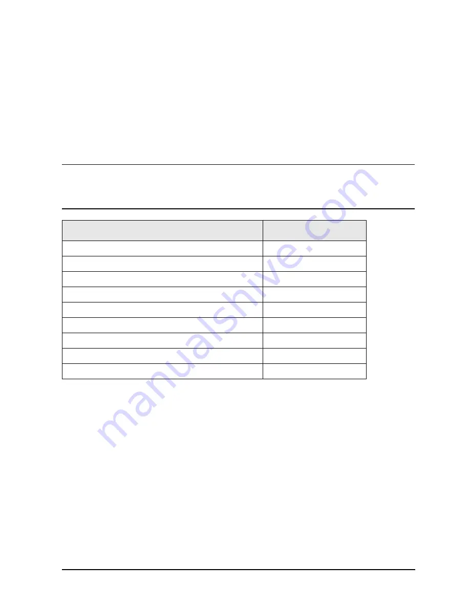
Board Assembly
1
1. Board assembly A9 troubleshooting is discussed further in the
the Frequency Offset Group (Option 080)” on page 4-54
.
Node Numbers
A12 source 20
111 to 118
A10 frequency reference
211 to 218
A11 phase lock
311 to 318
A8 fractional-N synthesizer
411 to 418
A16 test set motherboard, MA 20
511 to 518
A16 test set motherboard, SOMA 50
611 to 618
A16 test set motherboard, AUX 1
711 to 718
A16 test set motherboard, AUX 2
811 to 818
A9 fractional-N synthesizer (Option 080 only)
911 to 918
Содержание E8362B
Страница 11: ...Service Guide E8364 90026 1 1 1 Safety and Regulatory Information ...
Страница 19: ...Service Guide E8364 90026 2 1 2 General Product Information ...
Страница 33: ...Service Guide E8364 90026 3 1 3 Tests and Adjustments ...
Страница 83: ...Service Guide E8364 90026 4 1 4 Troubleshooting ...
Страница 151: ...Service Guide E8364 90026 5 1 5 Theory of Operation ...
Страница 185: ...Service Guide E8364 90026 6 1 6 Replaceable Parts ...
Страница 269: ...Service Guide E8364 90026 7 1 7 Repair and Replacement Procedures ...
Страница 351: ...Service Guide E8364 90026 8 1 8 General Purpose Maintenance Procedures ...


