


7-30
Service Guide E8364-90026
Repair and Replacement Procedures
PNA Series Microwave Network Analyzers
Removing and Replacing the A16 Test Set Motherboard
E8362B, E8363B, E8364B
Removing and Replacing the A16 Test Set Motherboard
Tools Required
• T-10 TORX driver (set to 9 in-lb)
• T-20 TORX driver (set to 21 in-lb)
• 5/16-inch open-end torque wrench (set to 10 in-lb)
• ESD grounding wrist strap
Removal Procedure
Refer to
for this procedure.
1. Disconnect the power cord.
2. Remove the outer covers. Refer to
“Removing the Covers” on page 7-6
. Position the
analyzer bottom side up and raise the receiver deck as shown. Refer to
Removing the Receiver Deck” on page 7-8
if necessary.
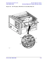
3. Remove the A21 SOMA 50 (E8363B and E8364B) or RF cable W1 (E8362B). Refer to
“Removing and Replacing the A21 SOMA 50 (E8363B and E8364B Only)” on page 7-40
.
4. Remove the A41 hard disk drive. Refer to
“Removing and Replacing the A41 Hard Disk
.
5. Remove the A41 hard disk drive shield by loosening two attachment screws using a T-10
TORX driver. These screws are accessible through holes in the side of the chassis.
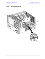
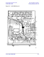
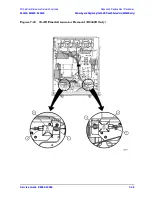
6. Disconnect the ribbon cables (item
①
) from the A16 test set motherboard.
7. Disconnect the wrapped-wire cables (item
②
) from the A16 test set motherboard.
8. Release the flexible RF cables from the cable clamp (item
③
). Release the receiver deck
by pulling the latch pin (item
④
), and move the entire receiver deck out of the way, with
the cables attached.
9. With a T-10 TORX driver, remove the following screws:
• Nine screws (item
⑤
) from the rear panel.
• Four screws (item
⑥
) from the A16 test set motherboard.
10.Slide the A16 test set motherboard toward the front of the instrument to release the
locking pins (item
⑦
), then lift the motherboard and remove it from the analyzer.
Replacement Procedure
1. Reverse the order of the removal procedure.
Note: When replacing the attachment screws, install the four screws in the
motherboard first, leaving them loose until the nine rear panel screws have been
tightened.
2. Perform the post-repair adjustments, verifications, and performance tests that pertain
to this removal procedure. Refer to
Содержание E8362B
Страница 11: ...Service Guide E8364 90026 1 1 1 Safety and Regulatory Information ...
Страница 19: ...Service Guide E8364 90026 2 1 2 General Product Information ...
Страница 33: ...Service Guide E8364 90026 3 1 3 Tests and Adjustments ...
Страница 83: ...Service Guide E8364 90026 4 1 4 Troubleshooting ...
Страница 151: ...Service Guide E8364 90026 5 1 5 Theory of Operation ...
Страница 185: ...Service Guide E8364 90026 6 1 6 Replaceable Parts ...
Страница 269: ...Service Guide E8364 90026 7 1 7 Repair and Replacement Procedures ...
Страница 351: ...Service Guide E8364 90026 8 1 8 General Purpose Maintenance Procedures ...


