


2-32
Using the Instrument
Analyzer Operating Modes
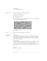
Switch Path Auto Align Now switches to the 9 µm filter mode path and performs an Auto Align.
This aligns the output of the monochromator with the photodetector input for improved ampli-
tude accuracy. The automatic alignment procedure should be performed whenever the instru-
ment has been:
• moved
• subjected to large temperature changes
• turned off, then on, and warmed up for an hour
The automatic alignment requires the connection of an external light source. This can be a broad-
band or narrowband source. If there is insufficient signal power, the automatic alignment will not
be performed and an error message will be reported.
The Auto Align function saves and restores the current instrument state. This allows the auto
align to be used in the middle of a measurement routine.
If markers are turned on, auto align attempts to do the automatic alignment at the wavelength of
the active marker.
N o t e
Auto Align Now will overwrite any previous align data.
The data returned by the alignment is stored for both the external (9 µm) and the internal (50 µm)
path. With the data stored for both paths, the alignment for the internal path is improved due to
the increased resolution bandwidth of the external path. Once the align is complete or if you
select No Auto Align, the instrument will be ready to detect data through the external path.
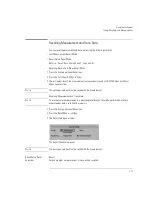
4 After the routine has finished, check that the display shows the wavelength range of interest of
the external path. Adjust if necessary.
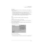
5 Press Res BW. Use the knob, step keys, or numeric keypad to enter the desired amount of
resolution bandwidth filtering.
The 9 µm optical path for filter mode uses the 0.04 nm resolution bandwidth. The resolution
bandwidths include 0.04 nm, 0.05 nm, 0.07 nm, 0.1nm, 0.2 nm, 0.3 nm, 0.5 nm, 1 nm, 2 nm, 5
nm, and 10 nm.
6 Press Take Sweep to update the display to show the results of the new resolution bandwidth
filtering.
The light is output from the optical spectrum analyzer’s front panel monochromator output con-
nector. This light is filtered (by the resolution bandwidth) and attenuated (by the monochromator
loss) light that is input to the front panel optical input connector.
7 Press Optical Filter Marker Tune. Turn the front panel knob or press the step keys to tune the
preselector to any displayed wavelength.
8 Connect the monochromator output to an instrument.
Содержание 8614 B Series
Страница 1: ...Agilent 8614xB Series Optical Spectrum Analyzer User s Guide ...
Страница 12: ...1 4 Getting Started Product Overview Agilent 8614xB Front and Rear Panels ...
Страница 13: ...1 5 Getting Started Product Overview ...
Страница 15: ...1 7 Getting Started Product Overview Figure 1 2 Display Annotations ...
Страница 16: ...1 8 Getting Started Setting Up the Analyzer Setting Up the Analyzer Step 1 Receive and Inspect the Shipment ...
Страница 26: ...1 18 Getting Started The Softkey Panels ...
Страница 31: ...1 23 Getting Started The Softkey Panels The Systems Menus continued ...
Страница 40: ...1 32 Getting Started Product Options and Accessories ...
Страница 75: ...3 Function Reference ...
Страница 186: ...4 16 Remote Front Panel Operation Remote Front Panel ...
Страница 226: ...6 2 Maintenance Changing the Printer Paper Changing the Printer Paper ...
Страница 264: ...7 16 Specifications and Regulatory Information Declaration of Conformity Declaration of Conformity ...
Страница 271: ......