


Chapter 1
Overview
OsmoTECH XT Single-Sample Micro-Osmometer Service Guide
13
Interfaces
The display PCB has the following interfaces:
•
RS-232
(1x): This serial interface communicates
commands and data to/from the control PCB.
•
USB 2.0 Type A
(2x): These interfaces allow a USB
device to be attached to the rear of the instrument via
internal shielded USB cables to USB adapter.
•
USB 2.0 Type B
(1x): This interface allows a USB device
to be attached to the rear of the instrument via
internal shielded USB cable to USB adapter.
•
Ethernet
(1x): This interface allows a 10/100 RJ45
cable to attach to the rear of the instrument via
internal shielded Ethernet cable to Ethernet adapter.
Non-volatile memory
The display PCB has non-volatile memory used to store
the last one thousand sample records.
The control PCB has non-volatile memory used to store
instrument set-up, calibration, and other pertinent data.
Real-time clock
The display PCB has a real-time clock and a back-up
battery to maintain the date, time, and firmware versions.
The instrument uses three proximity sensors to
determine the presence of sample tubes, objects near
the barcode scanner, thermoelectric module cooling,
activation of the solenoid, and the A/D reading of the
Wheatstone bridge circuits of the sample probe and
block probe.
Cradle switch assembly
The cradle switch is part of the sample handling
assembly. It informs the processor whether the cradle is
fully inserted or is pulled back.
RFID assembly
The RFID assembly reads and updates the count of
sample tips in the test kit box (part no. TECH250) and
allows test to begin when count is greater than zero.
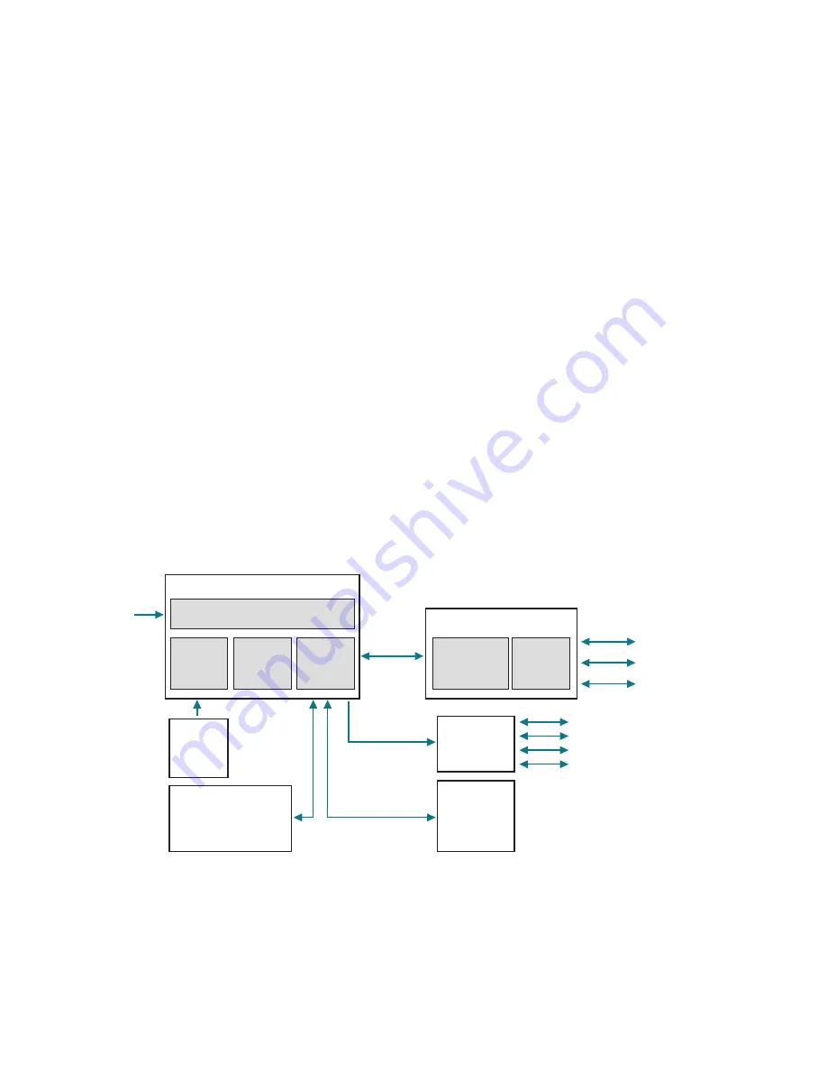
110V/220V
Power In
Serial
3 – USB A Ports
2 – Temperature Probes (24-bit)
1 – TEC Cooler
1 – Solenoid Impactor
1 – Cooling Fan
1 – USB B Port
1 – Ethernet Port
AC/DC
Power
Supply
Exhaust
Fan
Control
PCB
Power Entry Module
(Switch, Fused, Filtered)
Power/Control Box
Color/Touch
Display
Display
PCB
Display Box
Cradle
Switch
Assembly
Sample
Cooling
Assembly
RFID Assembly
Barcode
Scanner
1.5 Capturing screens to help with
troubleshooting.
Any instrument operator can capture the currently
displayed screen on the OsmoTECH XT to a USB drive.
This can be useful for a remote customer to capture
screens and send to a service technician to help
troubleshoot a system issue.
1.
Insert a USB drive in one the instruments’ USB ports.
2.
Press-and-hold on the top-right corner of the screen
until you hear a
click
sound to capture and save the
screen images to USB as a PNG file.


