


Manual Energy Storage Inverter ESI-S
Electrical design and installation 61
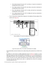
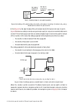
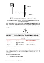
Interconnect the control boards of a following unit with a previous unit by an
RJ45-based communication cable. This cable is provided with each unit.
shows the way to interconnect the control boards.
Control board in the ‘previous’ unit
Control board in the ‘next’ unit
From previous unit (if present)
To next unit (if present)
Figure 46: Control board interconnection cable connection method.
−
The RJ45 control cable coming from the preceding unit is plugged in the left hand
side RJ45-socket at the top of the control board.
−
The RJ45 control cable leaving for the next unit is plugged in the right hand side
RJ45-socket at the top of the control board
−
Repeat the same procedure for any other inverters to be connected.
Notes:
−
In the first unit of a system, the left hand RJ45-socket will always be empty.
−
In the last unit of a system, the right hand RJ45-socket will always be empty.
−
During the commissioning phase, a unique address has to be assigned to each
unit in a system through dip switch (see
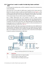
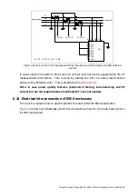
6.13.3 CT cable interconnection
WARNING: Failure to connect the CT’s to all units in a system in an appropriate way will
result in inverter malfunctioning and possibly sever damage of the unit.
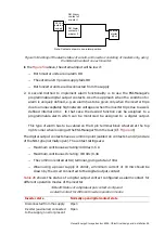
In a multi-unit ESI-S-system, all units have to be supplied with the CT –measurement
results. In order to do this the CT’s have to be cabled to each unit in a daisy chain fashion.
The connection principle is shown in
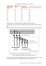
for the CT of phase which is fed to four
units. The same approach has to be implemented for the other phases too.


