


68 Electrical design and installation
Manual Energy Storage Inverter ESI-S
B
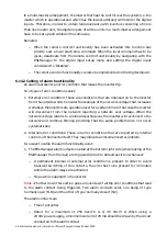
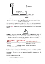
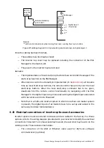
Note: Contacts drawn in non-alarm position
230 Vac
external
power
supply
NC Alarm
contact of
master 1
NC Alarm
contact of
master 2
Alarm bulb
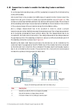
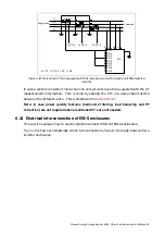
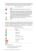
Figure 52: Cabling of the alarm status of a multi-unit inverter consisting of masters only, using
the NC alarm contact on each inverter.
In the
, the alarm bulb will be activated when both master units are in alarm.
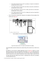
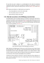
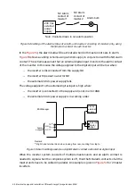
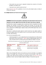
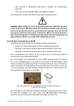
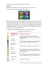
shows a cabling scheme using a 24 Vdc supply in conjunction with the NO alarm
contact. The scheme assumes that an external digital input monitors the alarm contact
of the inverter. In this case the voltage applied to the digital input will be low when:
−
the inverter is disconnected from the supply OR
−
the inverter trips due to an error OR
−
the external 24 Vdc power supply fails
The voltage applied to the external digital input is high when:
−
the inverter is connected to the supply and is not in error AND
−
the external 24 Vdc power supply is in working order
15
(a)
16
(a)
17
Alarm
outputs
NO
NC
24 Vdc
external
supply
Remark:
(a)
Right hand terminal block when looking from rear, counting from top to
bottom
External
digital
input
+
-
+
-
ESI-Manager
Figure 53: Alarm cabling example using NO alarm contact and external digital input
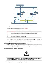
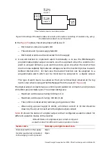
When the inverter system consists of multiple master-units and an alarm contact is
needed to signal when the complete system is off, then the NO alarm contacts of all the
master units have to be cabled in parallel. An example is given in
inverters.


