


122 The ESI-Manager user interface
Manual Energy Storage Inverter ESI-S
detection program will be quit. The CT parameters existing before the automatic
CT detection program was started will be restored.
If the CTs have been wrongly connected and the results are acknowledged by
the commissioning engineer, the inverter controller will automatically take into
account the wrong positions and correct them internally. Hence, there is no
need to correct the CT connections manually. However, in line with proper
installation guidelines, it may be recommended to correct physically the CT
installation. In that case, the CT setup of the inverter has to be adapted
accordingly.
−
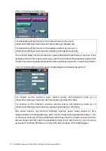
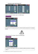
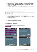
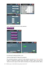
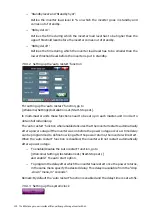
When the CT positions have been acknowledged the inverter will carry on by
showing the CT ratio found phase per phase. The values shown are indicative only
and always have to be verified by the commissioning engineer. He can change the
values by entering the right CT ratio. In order to approve the value entered
has to be pressed.
explains the meaning of the text that appears on the
display:
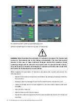
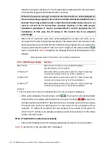
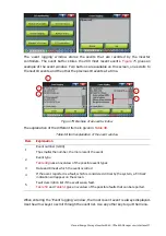
Table 46: Automatic CT detection ratio-results presentation
Text on ESI-Manager display Meaning
Ratio found
Ratio found for the CT in the considered phase
E.g. 200 means a CT of 1000/5
CT Ratio L1
(a)
Ratio that will be used by the inverter for the CT physically
connected in phase 1 (L1, R, U) of the installation
CT Ratio L2
(a)
Ratio that will be used by the inverter for the CT physically
connected in phase 2 (L2, S, V) of the installation
CT Ratio L3
(a)
Ratio that will be used by the inverter for the CT physically
connected in phase 3 (L3, T, W) of the installation
Remark:
(a)
The first phase has to be acknowledged before the second phase is displayed…
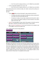
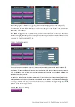
−
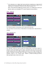
After acknowledging the last phase with
, the inverter will automatically
reset and the new values will be taken into account. Pressing
at any time
will interrupt the automatic CT detection process. In single unit inverters, original
CT-values and positions existing prior to the start of the procedure will be
restored. In multi-unit inverters, the new values will be stored in the units for
which the CT setting were already accepted, and will be restored to the initial
value in the other units.
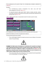
If the CT identification ended unsuccessfully
:
−
The inverter displays an error message indicating the reason for the problem.
gives a list of the possible error messages.


