


70 Electrical design and installation
Manual Energy Storage Inverter ESI-S
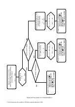
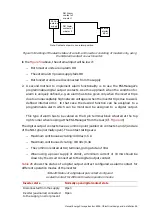
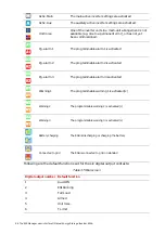
Inverter (auxiliaries) connected
to the supply, predefined error
appears
Closes when error present for 3 minutes.
Otherwise, contact remains open.
Inverter (auxiliaries) connected
to the supply, predefined error
disappears
When closed before, opens when error disappears.
When opened before, remains open.
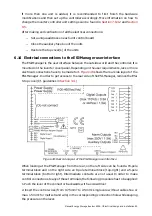
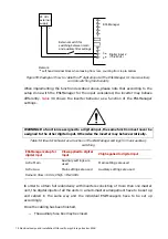
The alarm conditions that can be assigned to a digital output are given in
assignment must be made with the ESI-Manager. Any of the six digital outputs can be
used to cable an alarm. A maximum of 3 alarms can be assigned to the digital outputs.
Note however that by default the digital outputs have been set up for monitoring other
functions than alarms (cf.
) Refer to
Section 7.9.2.4.3
for guidelines on how to
navigate to the digital output setup menu.
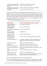
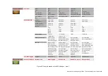
Table 27: List of possible alarm conditions that may trigger the alarm/digital outputs
Alarm condition
Criteria to be fulfilled before contact is activated
Supply voltage (RMS)
unacceptably high
Vrms_max > 110% Vnominal
Supply voltage (RMS)
unacceptably low
Vrms_min < 90% Vnominal
One of the phases of the supply
is missing
Vrms_min < 60% Vnominal
Network imbalance
unacceptably high
Vimbalance > 2%
Frequency variation
unacceptably high
Frequency variation > 20%/s
ESI-S DC bus voltage
unacceptably high
Vdc > 105% Vdc_max_allowed for each capacitor stack
ESI-S internal preload error
DC capacitor voltage rise too low in preload phase or the
DC capacitors could not be preloaded in an acceptable
time.
ESI-S over current fault
Internal current higher than allowed
ESI-S IGBT fault
IGBT hardware reports internal permanent error
ESI-S IGBT over temperature
IGBT hardware reports internal over temperature
Control board temperature too
high
Internal control board temperature probe reports too high
temperature
ESI-S internal power supply
fault
Internal control voltage too low or not present
ESI-S control board fault
Internal control board reports an error
ESI-S unit down (i.e. not
operational due to error)
Any of the units in a multi-unit arrangement is not running
although the start-command has been given.
Remark: the alarm trigger levels cannot be changed by the user.
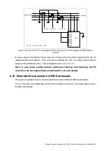
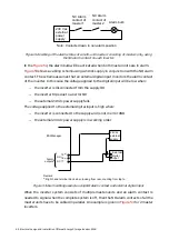
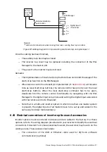
For cabling the digital output contacts as alarm contact, the same approach as shown
in
and can be adopted. Note however that the following behavior will result:


