


Manual Energy Storage Inverter ESI-S
Hardware description 31
Address 1: Position of the 3 switches starting from left: L L L
Address 2: Position of the 3 switches starting from left: H L L
Address 3: Position of the 3 switches starting from left: L H L
Address 4: Position of the 3 switches starting from left: H H L
Address 5: Position of the 3 switches starting from left: L L H
Address 6: Position of the 3 switches starting from left: H L H
Address 7: Position of the 3 switches starting from left: L H H
Address 8: Position of the 3 switches starting from left: H H H
Note: In a multi-master arrangement, the master is the unit which is
operational and which has the lowest address controls the system.
The default address setting is L L L
CAN bus termination (Right hand DIP switch):
Must be High (H) for the units that are at the extremity of the CAN
bus (maximum 2 units in a multi-unit inverters, typically the first one
and the last one of the chain). This setting is also applicable to
single-unit inverters.
Must be Low (L) for units in the middle of a chain.
The default factory setting is H.
Remarks:
(a)
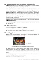
For physical locations of customer CT connection terminals, please refer to
Figure 16 item 4
.
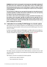
Table 14: ESI measurement board description
Item Description
Circuit diagram designation
1
230V supply of the power supply
P1
2
Flat cable to Cobo board
FC
3
15V
Power
supply
4
Voltage measurements (AC and DC)
P4 & P5
5 Current
measurement
P3
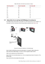
4.6.2 ESI inverter cover components
An ESI-S master panel cover (right hand side) contains the ESI-Manager user interface.
This interface is routed on to the main control board.


