


Project:
LV Energy Storage Inverters ESI
Issued by:
Commissioning report
Date:
Page 3 of 7
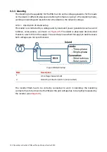
174 Commissioning instructions
Manual Power Quality Inverter ESI-S
•
Check visually the current transformers (if installed)
-
Ratio
-
Installed at the right side (feeding-side of the system)
•
For multi-unit system, check that the CTs of all units are cabled in a daisy chain fashion
with return path
(d)
•
Remove all jumpers of all current transformers (CTs and SCTs)
•
Remove all jumpers of the CT connection terminal(s) X21
Remarks:
(a)
Refer to
Section 8.2
of the manual for more information on this topic.
(b)
Refer to
Section 8.4
of the manual for more information on this topic.
(c)
Refer to
Section 8.3
of the manual for more information on this topic.
(d)
Refer to
Section 8.6.2.1
of the manual for more information on this topic.
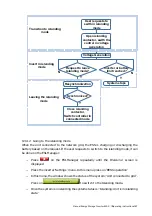
8.11.3 Programming
Apply voltage to the inverter
(a)
•
Close the auxiliary circuit fuse box
•
Refit the inverter protective cover including ESI-Manager connection
•
Apply voltage to the inverter (restore upstream protection)
•
ESI-Manager booting and showing ‘Welcome’ screen (or standby screen on
master units running as slave)
Program equipment
(b)
•
Network characteristics
−
Supply voltage (V)
−
Supply frequency (Hz)
−
Synchro mode (should normally not be changed, default value is Single
ph.)
•
inverter ratings
−
Connection mode (3-wire or 4-wire)
•
Battery limitations are set according to the battery specification
•
CT position and ratio (for first unit)
−
Automatic detection feature used
YES/NO
−
Inverter terminal ‘Input 1’ is connected to the CT (including sign)
(c)
Line 1, 2, 3, -1, -2, -3
−
Inverter terminal ‘Input 2’ is connected to the CT (including sign)
(c)
Line 1, 2, 3, -1, -2, -3
−
Inverter terminal ‘Input 3’ is connected to the CT (including sign)
(c)
Line 1, 2, 3, -1, -2, -3
−
Ratio of CT installed in line L1 (R, U)
−
Ratio of CT installed in line L2 (Y, V)
−
Ratio of CT installed in line L3 (B, W)
•
CT position and ratio for other units of a multi-unit system is ok?
•
Rating factor (temp > 40°C/104°F or altitude > 1000m/3300ft or…)
−
Rating (%)
•
Configure digital inputs if applicable
(d)
•
For full redundancy, configure/cable digital inputs on all masters of a multi-
master system
(d)
•
Configure digital outputs if applicable
(e)
•
For full redundancy, configure/cable digital outputs on all masters of a
multi-master system
(e)
•
Configure programmable warnings if applicable
(f)
•
For full redundancy, configure programmable warnings on all masters of a
multi-master system
(f)


