


50 Electrical design and installation
Manual Energy Storage Inverter ESI-S
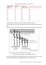
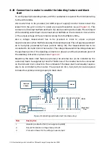
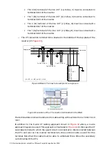
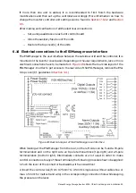
In order to connect the ESI-S in 3-wire mode, follow the below guidelines:
1. Fix the inverter mechanically to the wall (Cf.
Section 5.4
2. Ensure that an appropriately selected protecting device is connected upstream and
that the power supply cables are not live
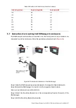
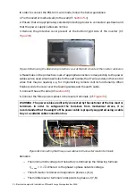
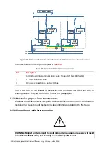
3. Remove the protective cover present at the bottom right side of the inverter (Cf.
Figure 33: Removing the Aluminum protective cover at the bottom side of the inverter enclosure
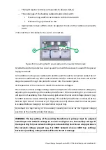
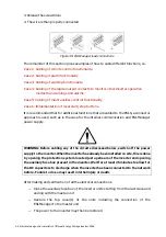
4. Make holes in the protective cover of appropriate section corresponding to the power
cable section used. Also make holes for the earth cable, the CT wire and any other control
wires that may be needed, e.g. for implementing remote control functionality. When
finished, slide the cover over the feeding cables and the earth cable.
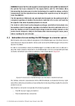
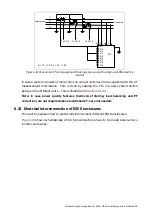
5. Connect the earth cable (Cf.
6. Connect the three power cables to the reactor terminals (Cf.
WARNING:
The power cables are directly connected by the customer at the line reactor
terminals. In order to safeguard the terminals from mechanical stress, it is
recommended that the weight of the power cable is properly supported using a cable
tray or a suitable cable connection box.
Figure 34: Connecting the three power cables to the inverter reactor terminals
Remarks:
−
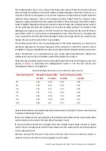
The minimum DC voltage for the battery is defined by the following formula:
= .
√
2
. Where U is the phase to phase network voltage.
−
The left reactor terminal corresponds to phase L1 (R, A)
−
The middle reactor terminal corresponds to phase L2 (Y, B)


