


Manual Power Quality Inverter ESI-S
The ESI-Manager user interface 83
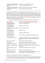
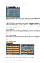
Tprobe alarm 1 to 8 can activate global alarm NO/NC relay
Warnings
Programmed warning can activate any digital output relay 1-6 if selected
Tprobe warning 1 to 8 can activate global fan NO relay
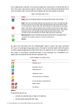
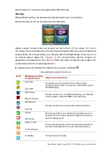
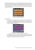
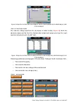
Digital output contact icons are located at the bottom of the screen (Cf.
).These icons are numbered 1 to 6 when they are disabled. If these output contacts are
programmed, the corresponding icon changes. When the ESI-Manager closes one of its
six digital output relays (Cf.
) the corresponding symbol changes its
appearance as described in the
. When the relay considered opens again, the
symbol takes back the original appearance.
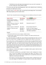
If a digital output is ‘Disabled’ the default icon is shown. Example:
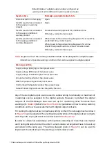
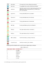
Table 36 Digital outputs status icons
Icons ESI-Manager
setting
for digital output
Output relay closes when…
Auxil. ON
Auxil. OFF
The auxiliary power is present in the main inverter
enclosure and the main controller is communicating with
the ESI-Manager
ESI running
ESI not running
The active inverter is ‘on’ (IGBTs switching) or in ‘standby’
(main contactor closed but IGBTs not switching)
Not full load
Full load
The active inverter is running under full load condition
Armed
Not armed
The inverter is ON or is in the start-up procedure, or it is
stopped in fault condition but will restart as soon as the
fault has disappeared
Within T limit
T limit reached
The inverter temperature limit has been reached and the
inverter is derating itself to run at a safe temperature
In standby
The inverter is in standby


