


100 The ESI-Manager user interface
Manual Energy Storage Inverter ESI-S
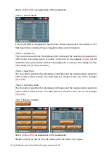
7.8.2.4.3 Harmonic table
The inverter current spectrum for all phases (3-W mode) and the neutral current
spectrum (4-W mode) in table format for the complete inverter system. The table layout
is similar to the one of the voltages (
) but only absolute current values are
shown.
Note: For a multi-unit inverter system, the total inverter current is an approximate value.
More detailed values for the individual units can be obtained in the ‘Inverter currents’-
menu.
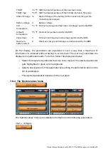
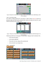
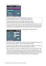
7.8.2.5 Powers
The power in the system at the location of the CTs: (Refer to
for an explanation
of the parameters).
−
Active power P
−
Reactive power Q
−
Apparent power S
−
Power factor PF
Displacement power factor cos
ϕ
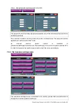
The power in the system at the location of the IGBT’s (inverter unit measurements):
(Refer to
for an explanation of the parameters).
−
Active power ESI P
−
Reactive power ESI Q
−
Apparent power ESI S
−
Active power P per phase (ESI P1, ESI P2, ESI P3)
−
Reactive power Q per phase (ESI Q1, ESI Q2, ESI Q3)
−
Apparent power S per phase (ESI S1, ESI S2, ESI S3)
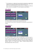
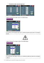
7.8.2.6 Temperatures


