


Manual Energy Storage Inverter ESI-S
Hardware description 15
—
4 Hardware description
4.1 What this chapter contains
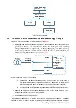
This chapter describes a typical ESI-S system and discusses its main components.
4.2 Typical ESI-S inverter panel layout
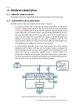
The ESI-S inverter is basically composed of two parts (
−
An inverter controller that is receiving the system information and adapt the
current or voltage output based on them. For some features that are described
in
, measurement of the line currents (network current) through current
transformers (CT’s) are required. The CT’s are provided by the customer. The CTs
must be connected upstream of the connection point of the inverter and the
loads. The user enters his requirements by means of the ESI-Manager user
interface. This device also acts as the user’s connection point for the
alarm/warning contacts, the remote control functionality, the other digital input
functionality and the interface for external communication.
−
A current/voltage generator (power unit) that converts the control signals
generated by the inverter controller into the inverter current or voltage. The
current/voltage generator is connected in parallel with the load(s). Up to four
power units may be connected in parallel in one f inverter system. The
enclosure(s) containing the inverter GUI controller are referred to as master units.
The other enclosures are referred to as the slave units. In an ESI-S system more
than one master unit can be present for redundancy purpose.
Loads:
- Three-phase
- Single-phase
Generation:
- Wind turbines
- Solar panels
ESI-S Main
controller
ESIManager
Current or
voltage
generator
Measurment
board
3
4
5
1
2
7
6
8
Supply
Figure 10: ESI-S schematic overview with user connections


