


Manual Energy Storage Inverter ESI-S
Electrical design and installation 47
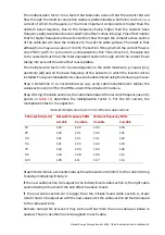
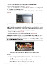
Table 22: RMS current ratings for protection fuses
Inverter nominal
current rating
(Arms)
Power rating
(kVA)
Minimum fuse
protection (Arms) Maximum fuse protection (Arms)
30
20
40
125
45
30
63
125
60
40
80
125
70
50
100
160
80
55
100
160
90
60
125
160
100
70
125
160
120
85
140
160
Voltage rating of the fuses should be according to the network voltage.
As an alternative to fuse protection, MCCB protection of appropriate sizing can also be
used.
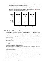
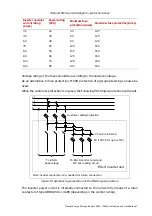
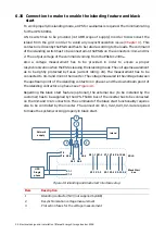
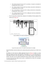
When the customer protection is in place, the following ESI-S input protection will result.
L1
L2
L3
To ESI-S
power stage
To ESI-S control circuit and
DC bus loading circuit
2.5mm² reinforced
6A (10X38 for up to 415V)
N
Customer added protection
ESI-S inverter unit
Note: neutral connection only needed for 4-wire connection
Figure 30: Symbolic representation of the ESI-S input protection
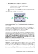
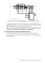
The inverter power circuit is internally connected to the network by means of a main
contactor of type ABB UA50 or UA95 (depending on the current rating).


