


62 Electrical design and installation
Manual Energy Storage Inverter ESI-S
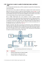
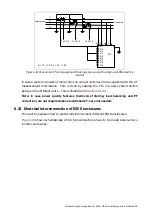
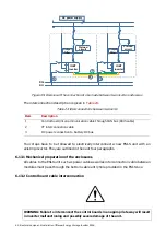
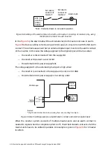
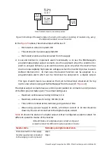
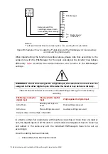
Figure 47: Principle of the CT interconnection circuit for multi-unit inverters
Note that the overall burden requirement for a complete system is 5 VA. To this value
has to be added the burden requirement of the interconnection cables to obtain the
total burden requirement of the CT’s to be used.
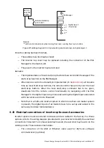
6.13.4 Connection of the power stage to the supply
As a final step in the interconnection process, the power stage of the new unit has to be
connected to the supply.
The same connection approach as used for the other units must be adopted. More
information on how to connect an ESI-S inverter unit to the power supply can be found
in
Section 6.8.
Regarding the power DC connection, each unit has its own connection to the battery
with its own DC switch.
WARNING: Make sure that the phase rotation of the power cable connection is
clockwise at the inverter terminals and that the L1, L2 and L3 terminal in each unit is
connected to the same phase for all units. Failure to do so may lead to the inverter
being damaged upon startup.
WARNING: Connect the correct polarity of the battery to the ESI. Wrong polarity of
battery may result in severe damage to the inverter and/or battery.
WARNING: Once a new unit has been added to a system, this unit has to be given a
unique address (through DIP switch setting on its control board). In addition, the unit
has to be recommissioned.


