


CI/AZ40-EN Rev. A
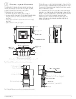
19
*Use 2-stage filtration only – required efficiency for 0.01 micron
(particles and droplets, installed in order) 93 % and 99.99 %.
**Gauges are required only at setup. If gauges are fitted permanently, a
shut-off valve should be used to prevent leakage from the gauge.
***Avoid locations near sources of heat – ambient temperature must not
exceed 49 °C (120 °F).
— Zero test gas should be the test gas of lowest oxygen content.
— Span test gas should be the test gas of highest oxygen content.
— For maximum accuracy, combine the highest CO test gas (CO span)
with the lowest (1 % nominal) oxygen test gas.
— The oxygen span gas should have the zero CO content
(CO zero).
— The oxygen span gas may be air (20.95 % O
2
) – recommended.
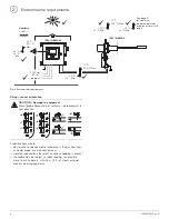
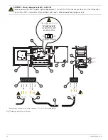
Item
Description
A
Instrument air supply to sensor assembly:
—
supply required: 350 to 700 ±10 kPa (50.0 to 100.0 ±1.5
psig)
—
the dew point at line pressure must be at least 10 °C (18 °F)
below the minimum local ambient temperature
at the plant site
—
maximum particle size in the air stream at the instrument
must not exceed 3 microns
—
maximum total oil or hydrocarbon content, exclusive of
non-condensables, must be as close as possible to 0 w/w %
or v/v %. – it must not exceed 1 ppm w/w or v/v under
normal operating conditions
B
Shut-off valve
C
2-Stage coalescing filtration (self-draining)*
D
Instrument air pressure regulator
E
3-Way valve (optional for maintenance purposes only,
not necessary for operation)
F
Aspirator suction pressure port:
—
pressure required at port:
–51.7 to –65.5 kPa (–7.5 to –9.5 psig)
G
Aspirator suction pressure gauge (Magnahelic)**:
—
pressure range: 0 to –69 kPa (0 to –10 psig)
H
Test gas port (sensor test gas inlet)
I
Probe filter / pressure gauge**:
— pressure range: 0 to 20 in H
2
O (inch WC)
J
Zero test gas (cylinder)***:
— mixed gas of O
2
/CO/N
2
balance
— nominal 1 % O
2
/ CO to be 80 to 100 % of the
CO range used
— must be certified for both O
2
and CO content
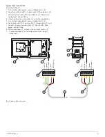
Table 3 Key to pneumatic installation schematic
K
2-Stage cylinder regulator for zero test gas
—
set to 1 bar (15 psig)
L
Span test gas (compressed air supply or cylinder)***:
— concentration of O
2
to be 80 to 100 % of the O
2
range
used
— compressed air supply may be used for a 0 to 25 %
O
2
range (recommended)
— cylinder gas must be certified for O
2
content
— compressed air line may be defined as 20.95 % O
2
M
2-Stage cylinder regulator for span test gas
—
set to 1 bar (15 psig)
N
Flowmeter, test gas line
Item
Description
Table 3 Key to pneumatic installation schematic (Continued)


