


16
CI/AZ40-EN Rev. A
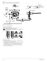
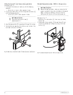
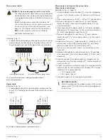
Customer-made connections at transmitter
DANGER – Serious damage to health / risk to life
The sensor power switch (SW1) supplies high voltage power (115 V or 230 V AC) to the sensor when set in the
ON
position.
It is fitted for operational purposes only and is
NOT
a transmitter safety isolation switch.
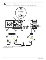
*Ensure mains connector is in correct position for application (115 V or 230 V)
Fig. 19 Customer-made connections at transmitter
DI1
DI2
DI3
DI4
A
C
COM
DC COM
1 2 3 4 5
6
N/C
C
N/O
N/C
C
N/O
N/C
C
N/O
N/C
C
N/O
N/C
C
N/O
N/C
C
N/O
1 2 3 4
+
–
+
–
+
–
+
–
1 2 3 4 5
V+
COM
D +
D –
SCN
1 – COM
2 – TX/RX–
3 – TX/RX+
4 – TX–
5 – TX+
Li
ne in
N
e
u
tr
a
l in
Earth
Li
ne out
Ne
ut
ra
l o
u
t
Earth
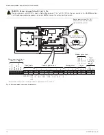
Digital inputs
Relays (digital outputs)
Analog outputs
Comms
Mains power connections –
see Fig. 17, page 14
Signal
connections
see Fig. 18,
page 15
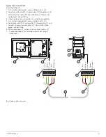
Modbus connections
High voltage power switch
transmitter to sensor
Sensor power switch (DO NOT
attempt to use as a transmitter
safety isolation switch)


