


18
CI/AZ40-EN Rev. A
5
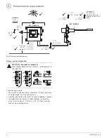
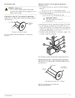
Pneumatic installation
Test gas and instrument air connections
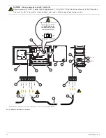
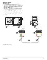
Fig. 21 Schematic – pneumatic installation
+
–
+
–
**
**
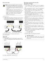
Mains power and
signal cables –
see page 12
Tubing line
arrangement
see NOTE below
Span gas***
regulated to 1 bar (15 psig)
Zero gas***
regulated to 1 bar (15 psig)
Pressure
regulator
set to
207 ±3 kPa
(30.0 ±0.5 psig)
Test gas to
sensor assembly
2-Stage
coalescing
filtration*
Test gas
flowmeter
Compressed
air supply
Instrument air supply
to sensor assembly
350 to 700 ±10 kPa
(50.0 to 100.0 ±1.5
psig)
Or
IMPORTANT (NOTE)
Slope tubing lines to sensor assembly 83.33 mm/m
(1 in/ft) minimum for a length of approximately 305 mm
(1 ft.) –
1
/
4
in. copper or stainless steel tubing only.


