


CI/AZ40-EN Rev. A
13
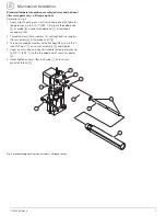
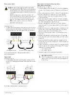
Mains power cables
Referring to Fig. 15:
1.
Prepare the incoming power cable and transmitter to sensor
power cable for connection by cutting back the outer PVC
sheathing and wire ends to the dimensions shown below:
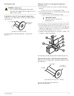
Signal cable
Referring to Fig. 16:
1.
Prepare both ends of the signal cable by cutting back the
outer PVC sheathing and wire ends to the dimensions shown
below:
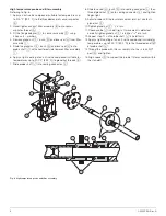
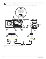
Mains power and signal cable connections
Mains power connections
Referring to Fig. 17, page 14:
1. Unlock and open transmitter door
A
using the supplied key,
unscrew 4 x PCB cover screws
B
and remove PCB cover
C
.
2. Check sensor power switch
D
is set to OFF (right position).
3. Remove cable gland (if used) at entry
E
and slide over
transmitter end of incoming mains power cable
F
in the
correct orientation.
4. Feed incoming mains power cable
F
(customer-supplied)
through entry
E
and connect to transmitter terminal block
G
. Refit cable gland (if used) at entry
E
.
5. Remove cable gland (if used) at entry
H
and slide over
transmitter end
I
of mains power cable
J
in the correct
orientation.
6. Feed transmitter end
I
of power cable
J
through entry
H
and connect to transmitter terminal block
K
. Refit cable
gland (if used) at entry
H
. Refit PCB cover
C
.
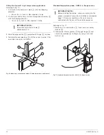
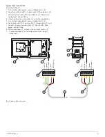
7. Unscrew 4 x sensor cover screws
L
and remove sensor
cover
M
.
8. Remove cable gland (if used) at sensor entry
N
and slide
over sensor end
O
of mains power cable
J
in the correct
orientation.
9. Feed sensor end
O
of power cable
J
through entry
N
and connect to sensor terminal block
P
. Refit cable gland (if
used) at entry
N
.
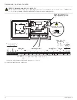
10.Check internal mains connector plug
Q
is plugged into the
correct socket for the supplied mains voltage (115 V [upper
socket] or 230 V [lower socket]).
— 115 V (upper socket)
— 230 V (lower socket)
11.Proceed to page 16 to make signal connections.
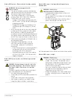
DANGER – Serious damage to health / risk to life
— The incoming mains supply cable must be isolated or
disconnected at the supply end of the cable before
making power connections at the transmitter and / or
sensor.
– Before making power connections between the
transmitter and sensor, set the sensor power switch
on the transmitter PCB to the OFF position – see
page 16. This internal switch on the transmitter is
NOT
a safety isolation switch and is fitted for
operational purposes only.
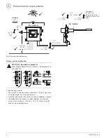
Fig. 15 Incoming mains power cable and transmitter to sensor
power cable preparation
Fig. 16 Signal cable preparation – transmitter to sensor
5 mm
(0.25 in.)
5 mm (0.25 in.)
50 mm
(2.0 in.)
50 mm (2.0 in.)
Incoming power cable
Transmitter to sensor power cable
Li
ne in
Neut
ral in
Earth
Li
ne out
Neu
tr
a
l ou
t
Earth
Li
ne in
Neut
ral in
Ear
th
5 mm (0.25 in.)
25 mm (1.0 in.)
Signal cable
D– (gr
een)
SCN (sc
reen)
D+ (whit
e
)
V+ (r
ed)
CO
M
(b
la
ck)
D– (gr
e
e
n
)
SCN (s
cr
een)
D+ (whit
e
)
V+ (r
ed)
COM (b
lack)
IMPORTANT (NOTE)
When all connections have been made, set the sensor
power switch
D
to the ON position to provide power
to the sensor.


