


10
CI/AZ40-EN Rev. A
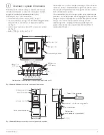
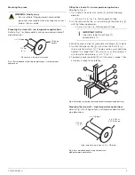
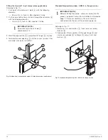
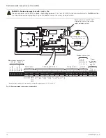
Fitting the stand-off – high temperature applications
Referring to Fig. 10:
1. Cut a hole in the outer wall / plate
A
with the following
diameter:
— 89 mm (3.5 in.) for 3 in. NB schedule 40 tube
2. On the same centre line, cut a hole through the refractory
B
with the following diameter:
— 76 mm (3 in.) for 3 in. NB schedule 40 tube
3. Weld the pipe section
D
(complete with flange
E
) in place.
4. Temporarily cover opening
F
until the sensor / probe / filter
assembly is ready for installation.
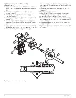
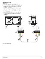
Standard temperature probe – ANSI 2 in. flange version
Referring to Fig. 11:
1. Remove 4 nuts and washers
A
from sensor assembly
threads
B
.
2. Feed probe / filter assembly
C
through flange
D
and
secure sensor body
B
to flange
D
using 4 nuts and
washers
A
.
IMPORTANT (NOTE)
If possible, taper the exit hole
C
approximately 15 °.
Fig. 10 Mounting – preparing the stand-off (high temperature applications)
15º
IMPORTANT (NOTE)
Before installing the probe / sensor assembly into the
process, complete transmitter installation as detailed on
page 12. Sensor assembly must have all services
connected with the transmitter ready for power up.
Fig. 11 Standard temperature probe – ANSI 2 in. flange version


