Parameters and firmware blocks
160
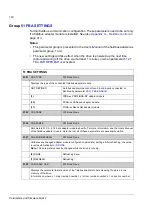
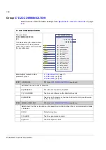
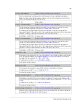
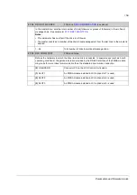
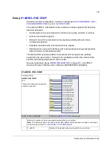
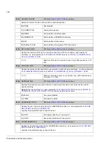
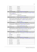
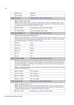
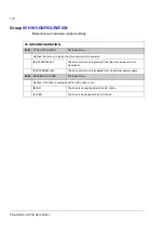
Group
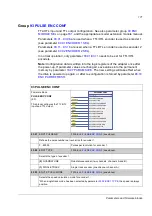
Settings for encoder activation, emulation, TTL echo, and communication fault
detection.
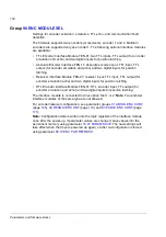
The firmware supports two encoders (or resolvers), encoder 1 and 2. Multiturn
encoders are supported only as encoder 1. The following optional interface modules
are available:
• TTL Encoder Interface Module FEN-01: two TTL inputs, TTL output (for encoder
emulation and echo) and two digital inputs for position latching
• Absolute Encoder Interface FEN-11: absolute encoder input, TTL input, TTL
output (for encoder emulation and echo) and two digital inputs for position
latching
• Resolver Interface Module FEN-21: resolver input, TTL input, TTL output (for
encoder emulation echo) and two digital inputs for position latching
• HTL Encoder Interface Module FEN-31: HTL encoder input, TTL output (for
encoder emulation and echo) and two digital inputs for position latching.
The interface module is connected to drive option Slot 1 or 2.
Note:
Two encoder
interface modules of the same type are not allowed.
For encoder/resolver configuration, see parameter groups
(page
),
(page
) and
(page
Note:
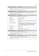
Configuration data is written into the logic registers of the interface module
once after the power-up. If parameter values are changed, save values into the
permanent memory using parameter
. The new settings will
take effect when the drive is powered up again, or after re-configuration is forced
using parameter
Содержание ACSM1 Series
Страница 1: ...ACSM1 Firmware Manual ACSM1 Speed and Torque Control Program...
Страница 2: ......
Страница 4: ......
Страница 12: ...Table of contents 12...
Страница 49: ...Drive control and features 49...
Страница 282: ...Standard function blocks 282...
Страница 306: ...Application program template 306...
Страница 312: ...Control chain block diagrams 312...
Страница 331: ...331...
Страница 332: ...332...
Страница 333: ......

