


Chapter 41 Diagnostic
XS1920 Series User’s Guide
362
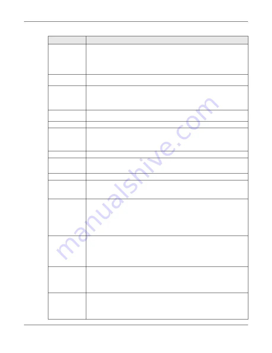
IPv4
Select this option if you want to trace the route packets take to a device with an IPv4
address, and select
vlan
to specify the ID number of the VLAN on which the Switch
traces the path. Otherwise, select
-
to trace the path on any VLAN.
Note: The device to which you want to run a traceroute must belong to the VLAN you
specify here.
IPv6
Select this option if you want to trace the route packets take to a device with an IPv6
address.
TTL
Enter the Time To Live (TTL) value for the ICMP Echo Request packets. This is to set the
maximum number of the hops (routers) a packet can travel through. Each router along
the path will decrement the TTL value by one and forward the packets. When the TTL
value becomes zero and the destination is not found, the router drops the packets and
informs the sender.
Wait Time
Specify how many seconds the Switch waits for a response to a probe before running
another traceroute.
Queries
Specify how many times the Switch performs the traceroute function.
IP Address/
Host Name
Enter the IP address or host name of a device to which you want to perform a
traceroute.
Click
Trace Route
to have the Switch perform the traceroute function. This determines
the path a packet takes to the specified device.
Ethernet Port Test Enter a port number and click
Port Test
to perform an internal loopback test.
Cable Diagnostics
Enter a port number and click
Diagnose
to perform a physical wire-pair test of the
Ethernet connections on the specified port(s). The following fields display when you
diagnose a port.
Port
This is the number of the physical Ethernet port on the Switch.
Channel
An Ethernet cable usually has four pairs of wires. A 10BASE-T or 100BASE-TX port only
use and test two pairs, while a 1000BASE-T port requires all four pairs.
This displays the descriptive name of the wire-pair in the cable.
Pair status
Ok
: The physical connection between the wire-pair is okay.
Open
: There is no physical connection (an open circuit detected) between the wire-pair.
Short
: There is an short circuit detected between the wire-pair.
Unknown
: The Switch failed to run cable diagnostics on the cable connected this port.
Unsupported
: The port is a fiber port or it is not active.
Cable length
This displays the total length of the Ethernet cable that is connected to the port when the
Pair status
is
Ok
and the Switch chipset supports this feature.
This shows
N/A
if the
Pair status
is
Open
or
Short
. Check the
Distance to fault
.
This shows
Unsupported
if the Switch chipset does not support to show the cable
length.
Distance to
fault
This displays the distance between the port and the location where the cable is open or
shorted.
This shows
N/A
if the
Pair status
is
Ok
.
This shows
Unsupported
if the Switch chipset does not support to show the distance.
Locator LED
Enter a time interval (in minutes) and click
Blink
to show the actual location of the
Switch between several devices in a rack.
The default time interval is 30 minutes.
Click
Stop
to have the Switch terminate the blinking locator LED.
Table 187
Management > Diagnostic (continued)
LABEL
DESCRIPTION
Summary of Contents for XS1920 Series
Page 18: ...18 PART I User s Guide ...
Page 32: ...32 PART II Technical Reference ...
Page 177: ...Chapter 21 Classifier XS1920 Series User s Guide 177 Figure 122 Classifier Example EXAMPLE ...
Page 408: ...Appendix C IPv6 XS1920 Series User s Guide 408 ...
Page 412: ...Appendix D Legal Information XS1920 Series User s Guide 412 Environmental Product Declaration ...


