For technical questions, please call 1-888-866-5797
16
About the
Scan Tool
DIS
PL
AY
FUNC
TIONS
3
5.
M (Menu)
button
– W
hen
pre
sse
d, d
isp
lay
s th
e M
ain
Men
u.
6.
LD button
–
When pressed
while
linked to
a vehicle,
places
the
Scan To
ol in
Live
Data mode.
7.
UP butto
n
– When
in ME
NU mode,
scrolls UP
through the
menu optio
ns. When
LINKED
to
a vehic
le,
scrolls
UP thro
ugh
the
current disp
lay screen
to disp
lay
any addit
iona
l data.
8.
ENTER
button
-
When in
Menu mode,
confirms
the selected
option or
value.
9.
DOWN
button
- W
hen
in
M
EN
U m
ode
, s
cro
lls
do
wn
thr
oug
h the
menu options.
When LI
NKED
to
a veh
icl
e, scr
olls do
wn throu
gh the
current disp
lay screen
to disp
lay
any addit
iona
l data.
10.GR
EEN
L
ED
-
Indicates tha
t
all eng
ine s
ystems are
runnin
g
normally (all
Monitors
on the
vehi
cle
are a
ctive and
performing their
diagnostic
testing,
and no
DTCs
are
present).
11.YEL
LOW
LE
D
-
Indicates there
is a
possible problem.
A “Pe
nding”
DTC
is pres
ent and/or
some of
the
vehicle's em
ission mon
itors
have
not run
their dia
gnostic testin
g.
12.RE
D L
ED
-
Indicates there
is a
problem in
one or
more o
f th
e
vehicle's
system
s. The
red LED
is al
so
used
to show
that DT
C(s)
are present.
DTCs are
show
n on
the Scan
Tool’s LCD
display.
In
this case,
the Malfunctio
n Indicator
(“Check
Eng
ine”)
lamp on
the
vehicle
's
ins
tru
men
t p
ane
l will
light steady
on.
13.Di
splay
- D
isp
lay
s te
st r
esu
lts
, S
can
T
ool
fun
ctio
ns
and
Mon
ito
r s
tat
us
info
rm
atio
n. S
ee
DIS
PLA
Y F
UN
CT
IO
NS
, b
elo
w, fo
r d
eta
ils
.
14.CABLE
- C
onn
ect
s th
e S
can
Too
l to
the
ve
hic
le'
s D
ata
Li
nk C
onn
ect
or
(DLC).
DISPLAY
FUNC
TIONS
Figure 2.
Display
Functions
See F
igure
2 for
the locations
of items
1 through
15, below.
1.
I/M M
ONIT
OR S
TA
TU
S f
ield
- Id
ent
ifie
s th
e I/
M Monitor
status area.
4
3
2
5
7
6
1
14
10
11
12
8
9
13
15
NETWORK TEST
Using the Scan Tool
NETWORK TEST
16
If the Scan Tool
cannot
link to the vehicle’s computer after three
attempts, the message “Contact Technical Support” displays.
- Press
SYSTEM MENU
to return to the System Menu.
- Turn the ignition off, and disconnect the Scan Tool.
- Contact Technical Support for assistance.
6.
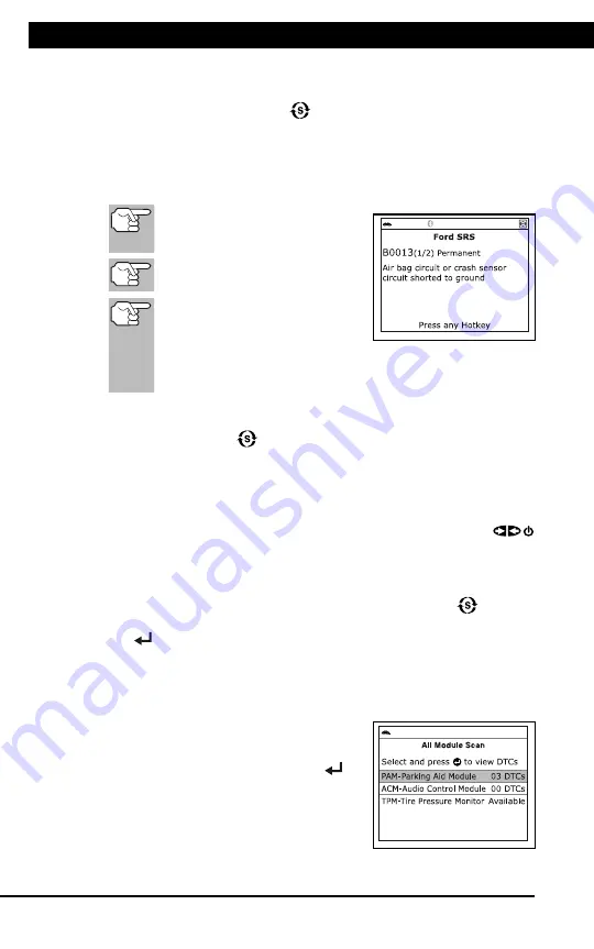
Refer to DISPLAY FUNCTIONS on page 2 for a description of LCD
display elements.
If the definition for the currently
displayed code is not available,
an advisory message shows.
I/M MONITOR STATUS icons
are not displayed when viewing
SRS DTCs.
In the case of long code
definitions, a small arrow is
shown in the upper/lower right-hand corner of the code
display area to indicate the presence of additional
information.
If no codes are present, the message "No SRS DTC’s are
presently stored in the vehicle’s computer" shows. Press the
SYSTEM MENU
button to return to the System Menu.
7.
If more than one code was retrieved press
DTC/FF
to display
additional codes one at a time.
Whenever the Scroll function is used to view additional codes, the
Scan Tool’s communication link with the vehicle’s computer discon-
nects. To re-establish communication, press
POWER/LINK
again.
8.
When the last retrieved DTC has been displayed and
DTC/FF
is
pressed, the Scan Tool returns to the “Priority” code.
To exit the enhanced mode, press
SYSTEM MENU
to return
to the System Menu. Select
Global OBD
, then press
ENTER
to return to the Global OBD2 mode.
NETWORK TEST
The Network Test lets you perform a scan of all vehicle modules, or of a
single selected module, to retrieve DTCs associated with the module(s).
To scan
all
modules:
1.
Select
All Module Scan
from the
System Menu, then press
ENTER
.
A “One moment please” message
displays while the Scan Tool scans
all available modules.
Summary of Contents for ZR13s
Page 1: ......


