For technical questions, please call 1-888-866-5797
17
About the Scan Tool
DISPLAY FUNCTIONS
3
5. M (Menu) button
– When pressed, displays the Main Menu.
6. LD button
– When pressed while linked to a vehicle, places the
Scan Tool in Live Data mode.
7.
UP button
– When in MENU mode, scrolls UP through the
menu options. When LINKED to a vehicle, scrolls UP through the
current display screen to display any additional data.
8.
ENTER button
- When in Menu mode, confirms the selected
option or value.
9.
DOWN button
- When in MENU mode, scrolls down through the
menu options. When LINKED to a vehicle, scrolls down through the
current display screen to display any additional data.
10. GREEN LED
- Indicates that all engine systems are running
normally (all Monitors on the vehicle are active and performing their
diagnostic testing, and no DTCs are present).
11. YELLOW LED
- Indicates there is a possible problem. A “Pending”
DTC is present and/or some of the vehicle's emission monitors have
not run their diagnostic testing.
12. RED LED
- Indicates there is a problem in one or more of the
vehicle's systems. The red LED is also used to show that DTC(s)
are present. DTCs are shown on the Scan Tool’s LCD display. In
this case, the Malfunction Indicator (“Check Engine”) lamp on the
vehicle's instrument panel will light steady on.
13. Display
- Displays test results, Scan Tool functions and Monitor status
information. See DISPLAY FUNCTIONS, below, for details.
14. CABLE
- Connects the Scan Tool to the vehicle's Data Link Connector
(DLC).
DISPLAY FUNCTIONS
Figure 2. Display Functions
See Figure 2 for the locations of items 1 through 15, below.
1. I/M MONITOR STATUS field
- Identifies the I/M Monitor status area.
4
3
2
5
7
6
1
14
10
11
12
8
9
13
15
NETWORK TEST
Using the Scan Tool
CONNECTING TO BLUETOOTH / WIFI
17
If you have not yet established an account, you must register for
a FREE RepairSolutions 2 account before proceeding.
3.
Connect the Code Reader to a vehicle and establish a Bluetooth or
WiFi connection with your Smart Device (refer to CONNECTING TO
BLUETOOTH / WIFI, below). Be sure your Smart Device is
connected to an available WiFi network.
The RepairSolutions 2 app will store two WiFi configurations
only.
4.
Retrieve diagnostic data (refer to CODE RETRIEVAL PROCEDURE
on page 6 for details).
5.
The RepairSolutions 2 app automatically displays a report based on
the retrieved diagnostic data.
If the Code Reader is not connected to WiFi or Bluetooth,
vehicle data will not be saved.
CONNECTING TO BLUETOOTH / WIFI
Launch the RepairSolutions
2 app an follow the prompts to
establish Bluetooth and (optionally) WiFi connections, as follows:
1.
Launch the RepairSolutions
2 app. Select
Wifi Tools Settings
from
the menu. Power on your Code Reader, then select from the
list of
available devices.
2.
When Bluetooth pairing is complete, a confirmation screen displays.
Click
Continue
.
If a Bluetooth connection cannot be established, an advisory
message displays. Tap
Try Again
to repeat the pairing process.
3.
Follow the on-screen prompts to connect to an available WiFi
network.
You can automatically connect to the network your Smart Device
is currently connected to, or you can manually connect to
another available network.
Note that only 2.4GHz networks are supported.
If you do not wish to connect to a WiFi network at this time, tap
SKIP
.
4.
When WiFi pairing is complete, a confirmation screen displays. Click
Continue
to view the “Setup Complete” message, then click
Continue
to enter RepairSolutions
2.
If a WiFi connection cannot be established, an advisory
message displays. Tap
Try Again
to repeat the pairing process.
Using the Scan Tool
NETWORK TEST
17
When the scan is complete, the Available Systems screen
displays. The screen shows the number of DTCs recorded for
each available module.
2.
Select the module for which you wish to view DTCs, then press
ENTER
. A “One moment please” message displays while the
requested DTCs are retrieved.
If the Scan Tool fails to link to the selected module, a
“Communication Error” message shows.
- Ensure your vehicle is OBD2 compliant.
- Verify the connection at the DLC, and verify the ignition is ON.
- Turn the ignition OFF, wait 5 seconds, then back ON to reset
the computer.
- Press
POWER/LINK
to continue, or, press
System
Menu
to return to the System Menu.
If the selected module does not support the “Read DTC” function,
an advisory message displays. Press
System Menu
to
return to the System Menu, or, press
M
to access the Main
Menu.
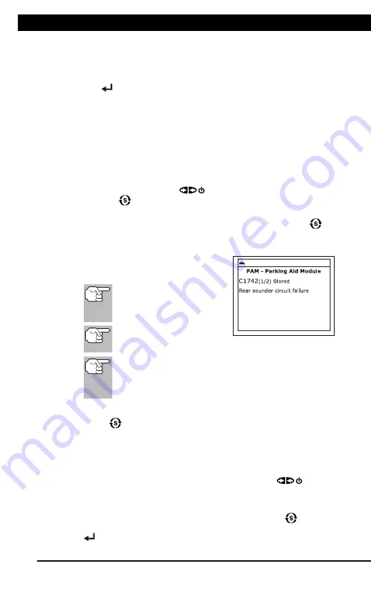
3.
Refer to DISPLAY FUNCTIONS on
page 3 for a description of LCD display
elements.
If the definition for the
currently displayed code is
not available, an advisory
message shows.
I/M MONITOR STATUS
icons are not displayed
when using the Network Test function.
In the case of long code definitions, a small arrow is
shown in the upper/lower right-hand corner of the code
display area to indicate the presence of additional
information.
If no codes are present, the message "No (
system name
) DTC’s are
presently stored in the vehicle’s computer" shows. Press
System
Menu
to return to the System Menu.
4.
If more than one code was retrieved press
DTC/FF
to display
additional codes one at a time.
Whenever the Scroll function is used, the Scan Tool’s
communication link with the vehicle’s computer disconnects. To
re-establish communication, press
POWER/LINK
again.
5.
When the last retrieved DTC has been displayed and
DTC/FF
is
pressed, the Scan Tool returns to the first code.
To exit the enhanced mode, Press
System Menu
to return
to the System Menu. Select
Global OBD
, then press
ENTER
to return to the Global OBD2 mode.
Summary of Contents for ZR13s
Page 1: ......


