66 / 121
User Manual 3000SP
Rev. 1.1 16/03/2021
Identification: MD-AL-GI-00
Rev. 1.1 of 16/03/2021 - Application: GID
7.1.
CT / Battery Communication / RS485 Connections
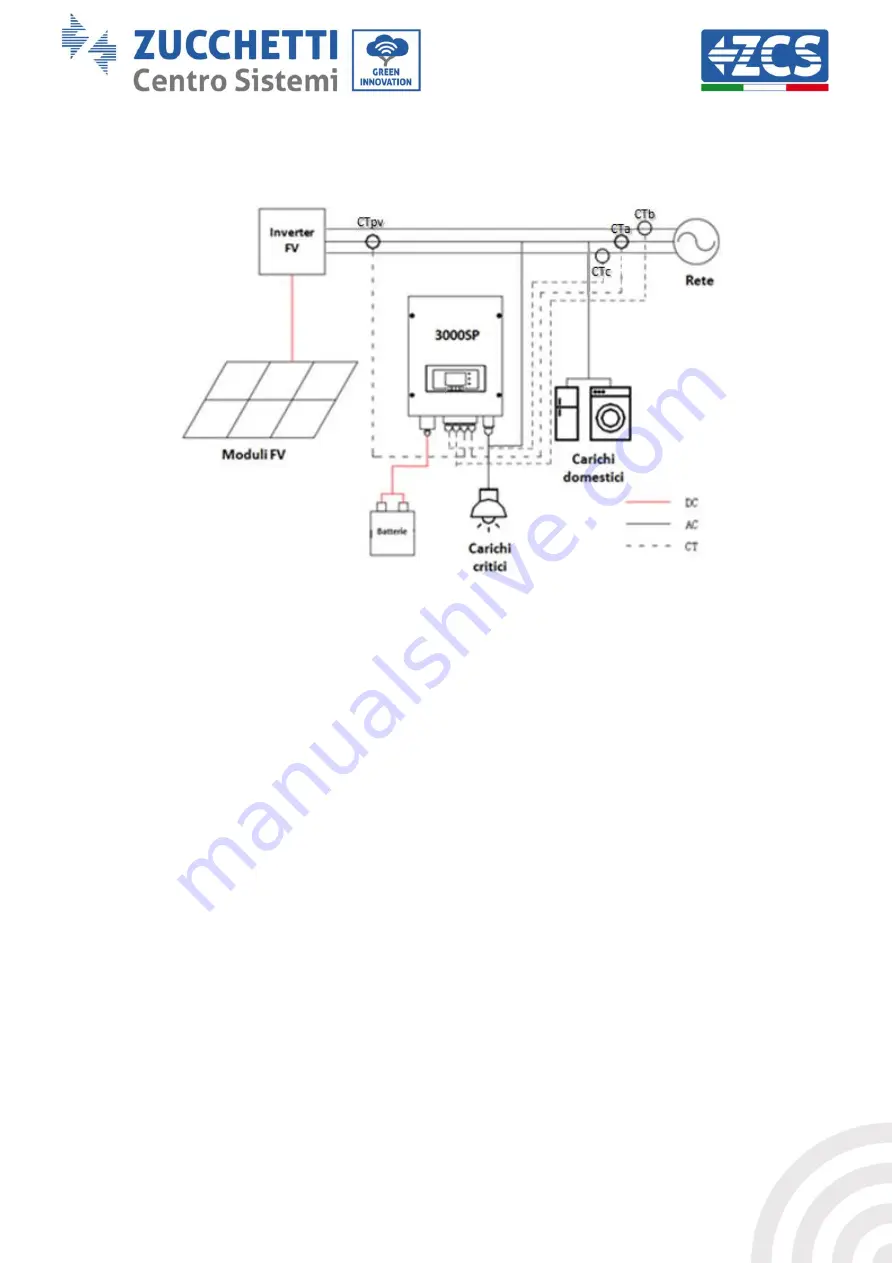
Figure 43 – Wiring diagram of the 3000SP storage inverter inside a system powered by renewable energy
9)
Correctly position the four current sensors (CT):
- the CTa for measuring the energy exchanged with the grid must be positioned at the output of the
exchange meter (utility side) on the same phase where the storage unit has been installed, and must
include all the phase cables entering or leaving the meter. The CTa will therefore measure both the
energy fed into the grid by the photovoltaic system and the energy withdrawn to meet the
requirement of the utilities on its phase.
- the CTb and CTc, each positioned on the other two phases, must include all phase cables entering or
leaving the meter. The CTb and CTc will measure both the energy fed into the grid by the
photovoltaic system and the energy withdrawn to meet the requirement of the utilities, each on its
own phase.
- The CTpv for measuring the photovoltaic production must be positioned on the phase cable exiting
the photovoltaic inverter (utility side) or from the production meter, and will only measure the
energy generated by the photovoltaic inverter. The CTpv must be positioned on the phase where the
3000SP inverter is installed.


