108
/
152
Plug ports A and C with self-made head, and check the sealing by ventilation from port C. Inject the gas with a pressure of
160kPa (1.63Kgf/cm2, 23.2 psi) to ensure that there is no air leakage at the nozzle. Immerse the water tank in the water for 10s
and observe whether there are bubbles.
Check whether the fan and the mesh cover are firmly
assembled, and the rotating fan blades should be free
of stagnation. Check whether the buffer rubber is aged
and cracked. Check whether the fan cable is damaged
The fan plug is positive in blue and negative in black.
Find the battery with sufficient power, connect the
wires according to the positive and negative poles, and
check whether the fan draws air backward
Compressed air with lower air pressure can be blown
from the back to the water tank from a long distance to
clean up foreign objects on the surface. Or use a low-
pressure water gun to spray the radiating fins from a
long distance to clean up foreign objects on the surface.
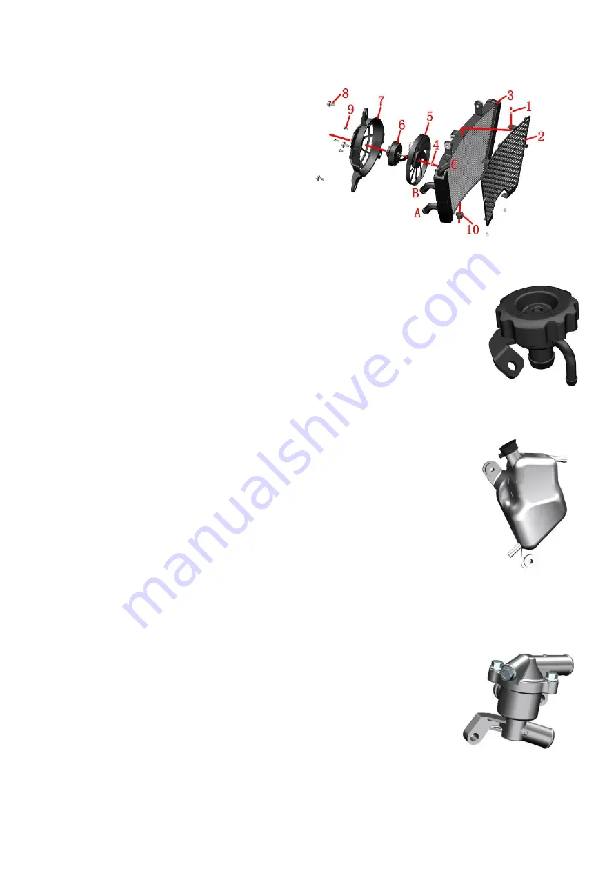
1 - Water tank front cover screw * 3 2 - Water tank front cover 3 - Water tank 4 - Fan sheet nut 5 - Fan sheet 6 - Fan
motor 7 - Fan cover 8 - Fan cover bolt * 3 9 - Fan motor bolt * 3 10 - Buffer rubber
2. Attention to the water tank filling port
Caution:
●Special ventilation tooling (gas pressure reducing valve, air gun, sealing tube) is required for testing.
●After the soaking inspection is completed, the water stains should be wiped clean in time.
2.1 Overall tightness inspection
Seal the small pipe and ventilate to the large pipe for air tightness inspection. The gas with a pressure
of 160kPa (1.63Kgf/cm2, 23.2 psi) is introduced to ensure that there is no air leakage at the nozzle, and
the water inlet is put into the water for 10s to observe whether there are bubbles.
2.2 Pressure relief valve inspection
Introduce 100kPa (1.02Kgf/cm2, 14.5 psi) compressed air into the large pipe, put the water inlet into the water for 10s, and
the small pipe should be free of bubbles. When the compressed air is raised to 110kPa (1.12Kgf/cm2, 16 psi), bubbles should
appear.
3. Auxiliary water tank
First check whether the rubber cover is aging and cracked, if any, replace it. If the appearance is
good, then check the air tightness.
Seal the two small water outlets and open the black plastic cover of the water tank for air tightness
inspection.
Continue to seal the small water outlet, fill the auxiliary tank with water and turn the auxiliary tank
upside down, and observe whether the rubber cover of the water tank seeps. If there is seepage, it is
unqualified. Pour out the water after checking the tightness, remove the plug and let the auxiliary
water tank dry naturally or blow it dry with a dust blower.
4. Water and oil shared sensor
For details on sensor detection and disassembly methods, please refer to the section "Electronic Injection System" chapter EFI
Parts Fault Diagnosis and Elimination.
5. Thermostat
5.1 Inspection
Check the appearance for damage and leakage.
Simple test method (test on the whole vehicle):
After the cold car is started, immediately open the water filler cap. If there is no fluctuation in
the liquid level, the thermostat is normal, otherwise it is abnormal. Check that when the water
temperature is lower than 70°C (158 F), the thermostat should be in a closed state. When the
temperature is higher than the initial opening temperature, the expansion valve of the expansion
cylinder will gradually open, and the circulating coolant in the radiator will begin to flow.
After the temperature rises, check the inlet pipe of the small water tank. You should be able to
clearly feel the signs of water flow or the temperature of the pipe wall, otherwise the pump or
waterway will be blocked.
When the temperature reaches 80°C (176 F), the heating rate slows down, and the thermostat works normally. If the water
temperature has been rising rapidly, when the internal pressure reaches a certain level, the sudden overflow of boiling water
indicates that the valve is stuck.
If it is stuck or closed loosely, it can be removed and cleaned or repaired first, otherwise it should be replaced.
Summary of Contents for ZT350T-D
Page 1: ...1 152 ZT350T D Maintenance Manual 2022 11 24...
Page 50: ...50 152 D350 Braking system component diagram...
Page 88: ...88 152 Electrical schematic diagram of EFI system...
Page 124: ...124 152 Exploded view of front fork components Directional exploded view...
Page 125: ...125 152 Front fork exploded view...


