background image

Administrator’s Guide for Yealink VC110 Video Conferencing Endpoint 

218


2.


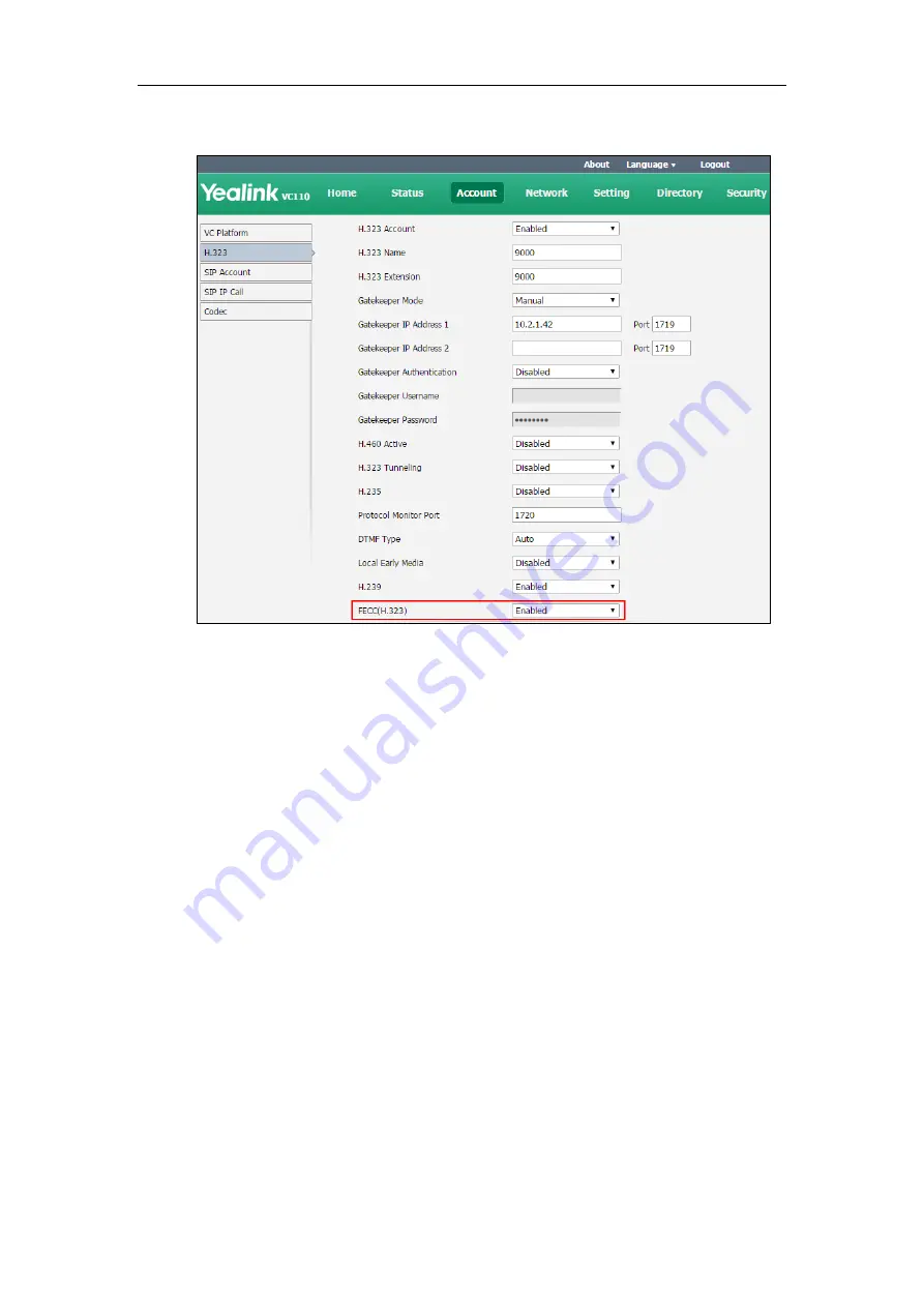
Select the desired value from the pull-down list of 

FECC(H.323)


3.


Click

 Confirm

 to accept the change. 

To configure FECC(SIP) camera control protocol for Zoom

/

Pexip

/

BlueJeans

/

Mind

/

Custom 

platform via web user interface:


1.


Click on 

Account->VC Platform

2.


Select

 Zoom

/

Pexip

/

BlueJeans

/

Mind

/

Custom

 from the pull-down list of

 Platform Type


Summary of Contents for CPE80

Page 1: ......

Page 2: ...y form or by any means with any purpose other than personal use Warranty 1 Warranty THE SPECIFICATIONS AND INFORMATION REGARDING THE PRODUCTS IN THIS GUIDE ARE SUBJECT TO CHANGE WITHOUT NOTICE ALL STATEMENTS INFORMATION AND RECOMMENDATIONS IN THIS GUIDE ARE BELIEVED TO BE ACCURATE AND PRESENTED WITHOUT WARRANTY OF ANY KIND EXPRESS OR IMPLIED USERS MUST TAKE FULL RESPONSIBILITY FOR THEIR APPLICATIO...

Page 3: ...product is available on the Yealink Support page for the product Patent Information China the United States EU European Union and other countries are protecting one or more patents of accompanying products and or patents being applied by Yealink Customer Feedback We are striving to improve our documentation quality and we appreciate your feedback Email your opinions and comments to DocsFeedback ye...

Page 4: ......

Page 5: ...performance in the network Therefore an understanding of IP networking and a prior knowledge of VoIP telephony concepts are necessary See the Yealink Products Regulatory Notices Guide for all regulatory and safety guidance Documentations This guide covers the VC110 video conferencing endpoint In addition to the administrator guide the following related documents are available Quick Start Guide whi...

Page 6: ...n the endpoint Chapter 5 Configuring Endpoint Settings describes how to configure basic audio and video features on the endpoint Chapter 6 Endpoint Management describes how to manage endpoint contacts and call history Chapter 7 Configuring Security Features describes how to configure security features on the endpoint Chapter 8 Endpoint Maintenance describes how to upgrade endpoint firmware and res...

Page 7: ... notice that the same terms are used repeatedly Make sure you familiarize yourself with these terms Cloud platform This term refers to Yealink VC Cloud Management Service Yealink Cloud Yealink Meeting Server Zoom BlueJeans Pexip Mind and Custom platform Cloud account This term refers to Yealink Cloud YMS BlueJeans Pexip Mind and Custom account Cloud systems This term refers to the systems that sup...

Page 8: ...curred to the following sections Intelligent Firewall Traversal on page 99 Default Layout on page 168 Changes for Release 22 Guide Version 22 15 The following section is new for this version Logging into the StarLeaf Cloud Platform on page 114 Major updates have occurred to the following sections H 323 Tunneling on page 82 Enabling H 460 Support for H 323 Calls on page 142 Methods of Transmitting ...

Page 9: ...Major updates have occurred to the following sections Icon Instructions on page 33 Setup Wizard on page 49 Directory on page 231 Changes for Release 21 Guide Version 21 15 The following section is new for this edition IPv6 Support on page 64 Video Codecs on page 152 Hiding Icons in a Call on page 185 Output Resolution on page 221 Video Recording on page 223 Screenshot on page 225 Major updates hav...

Page 10: ...ink VC110 Video Conferencing Endpoint x Changes for Release 10 Guide Version 10 11 Major updates have occurred to the following sections Codecs on page 150 Configuring Camera Settings on page 206 Camera Control Protocol on page 215 ...

Page 11: ...21 15 ix Changes for Release 10 Guide Version 10 11 x Table of Contents xi VC110 Video Conferencing Endpoint Introduction 1 VoIP Principles 1 Physical Features of Endpoint 2 Packaging Contents 3 VC110 All in one Package 4 VCM60 Package 5 VCP40 Package 6 VCP41 Package 7 VCM30 Package 8 Endpoint Component Instructions 8 VC110 All in one Unit 9 Cable Hub 12 VCM60 Video Conferencing Wireless Microphon...

Page 12: ...point 54 Configuring Network 55 Preparing the Network 55 Configuring LAN Properties 56 DHCP 56 Configuring Network Settings Manually 61 IPv6 Support 64 Configuring Network Speed and Duplex Mode 68 VLAN 70 LLDP 71 Manual Configuration for VLAN 74 DHCP VLAN 75 802 1X Authentication 77 H 323 Tunneling 82 Configuring the Endpoint for Use with a Firewall or NAT 86 Call Setup and Media Ports 86 Restrict...

Page 13: ...Methods of Transmitting DTMF Digit 145 Codecs 150 Audio Codecs 150 Video Codecs 152 Call Protocol 153 Account Polling 155 Do Not Disturb 157 Auto Answer 158 Auto Dialout Mute 159 Call Match 160 History Record 161 Bandwidth 162 Sharing Content 164 Ringback Timeout 165 Auto Refuse Timeout 166 SIP IP Call by Proxy 166 Default Layout 168 Public Mode 169 Configuring Endpoint Settings 171 General Settin...

Page 14: ...ion 222 Video Recording 223 Screenshot 225 Tones 226 Endpoint Management 231 Directory 231 LDAP 235 Call History 240 Search Source List in Dialing 242 Dual Display Screen Layouts 243 Two way Video Calls 243 Two way Video Call with Presentation 244 Endpoint Integrated with Control Systems 244 Using the API with a LAN Connection 244 Using the API with a Serial Connection 245 Configuring Security Fea...

Page 15: ...kets 282 Getting Information from Status Indicators 285 Analyzing Configuration Files 285 Viewing Call Statistics 286 Using Diagnostic Methods 286 Troubleshooting Solutions 288 General Issues 289 Camera Issues 290 Video Audio Issues 291 Why does the far site display black screen when local starts a presentation 293 Endpoint Maintenance 294 Appendix 297 Appendix A Time Zones 297 Appendix B Trusted ...

Page 16: ...Administrator s Guide for Yealink VC110 Video Conferencing Endpoint xvi ...

Page 17: ...ues for the delivery of voice communications and multimedia sessions over IP networks The H 323 and Session Initiation Protocol SIP are two popular VoIP protocols that are found in widespread implementation H 323 H 323 is a recommendation from the ITU Telecommunication Standardization Sector ITU T that defines the protocols to provide audio visual communication sessions on any packet network The H...

Page 18: ...e ability to control the attributes of an end to end call Physical Features of Endpoint Video conferencing endpoints are in the overall network topology which are designed to interoperate with other compatible equipment including application servers media servers Internet working gateways and other endpoints In order to operate endpoints in your network successfully the endpoints must meet the fol...

Page 19: ... Full HD 1080P at 30fps 1920x1080 from 1Mbps 720P 1280x720 from 512Kbps W448P 768 x 448 WQVGA 400 x 240 4CIF 704 576 CIF 352 x 288 Packaging Contents We provide the following packaging contents You can purchase any combination according to your needs VC110 Package VC110 Package VCM60 Package VC110 Package VCP40 Package VC110 Package VCP41 Package VC110 Package VCM30 Package Note We recommend that ...

Page 20: ...10 Video Conferencing Endpoint 4 VC110 All in one Package VC110 All in one Unit Cable Hub L Bracket for installing the VC110 one in one unit Mounting Accessories for installing the VC110 one in one unit VCR10 Remote Control AAA Batteries 2 ...

Page 21: ...VC110 Video Conferencing Endpoint Introduction 5 Power Adapter Cables Velcro 2 Cable Ties 5 VC110 Quick Start Guide VCM60 Package VCM60 Video Conferencing Wireless Microphone Power Adapter ...

Page 22: ...e Ethernet Cable 7 5m Locate the Audio In port of the cable hub and connect it to the Audio Out port of the VCP40 video conferencing phone with the 7 5m Ethernet cable VCP40 video conferencing phone can work as an audio device for the VC110 endpoint You can also place calls answer calls or view directory and history on the VCP40 video conferencing phone ...

Page 23: ...cting a PC Mobile device to the VCP41 Locate the Audio In port on the cable hub and connect it to the Audio Out port of the VCP41 video conferencing phone with the 7 5m Ethernet cable VCP41 Video conferencing phone can work as an audio device for the VC110 endpoint You can also place calls answer calls or view directory and history on the VCP41 video conferencing phone ...

Page 24: ...r the VC110 endpoint For more information refer to Audio Input Device on page 195 Note Endpoint Component Instructions Before installing and using the VC110 video conferencing endpoint you need to be familiar with the following endpoint components including VC110 All in one Unit Cable Hub VCM60 Video Conferencing Wireless Microphone Video Conferencing Phone CPE80 Expansion Microphone VCM30 Video C...

Page 25: ...ay devices automatically Lens cover The lens cover is used for protecting the lens which shall not receive dust pollution and all possible brush collision The front of VC110 all in one unit The HD camera supports 4xdigital zoom white balance and automatic gain You can place the VC110 all in one unit on the table or mount it on a wall The LED indicator in front of the camera indicates different sta...

Page 26: ...ne of the two USB ports for storing screenshots recording videos or capturing packets Inserts a dongle to one of the two USB ports for connecting the VCM60 video conferencing wireless microphone Note The wireless microphone dongle and USB flash drive can work at the same time If two USB flash drives are connected only the latter one can be identified When the endpoint is powered on avoid physicall...

Page 27: ...it Port Name Description Reset Key Resets the endpoint to factory defaults DVI Port Connects to the cable hub Display1 Connects to a display device for displaying video images When connecting to only one display device Display1 port on the VC110 all in one unit is the only available port Display 2 Connects to secondary display device for displaying video images Line In Connects to an audio input d...

Page 28: ...C Connects to a PC for sharing documents or videos during a call The back of cable hub Port Name Description DVI Port Connects to the VC110 all in one unit VCM60 Video Conferencing Wireless Microphone The VCM60 is a video conferencing wireless microphone which can work as the audio input device for VC110 video conferencing endpoint It supports 360 degree audio pickup at a radius of up to 2 meters ...

Page 29: ... dongle when it is in the offline standby mode For more information refer to Standby Mode on page 33 Enters registration mode For more information refer to Registering and Unregistering the VCM60 on page 18 Charging Interface Connects the VCM60 to a power adapter or a computer s USB port using a USB cable to charge the VCM60 Switch Turns on or off the VCM60 Placing the VCM60 The VCM60 has a rubber...

Page 30: ... dongle automatically You can turn off this switch if the VCM60 is not in use for a long period of time Connecting VCM60 to the Video Conferencing Endpoint To ensure good voice quality VCM60 video conferencing wireless microphone can be connected to the VC110 video conferencing endpoint to work as the audio input device To connect the VCM60 to the VC110 video conferencing endpoint do the following...

Page 31: ...on the status bar 2 Turn on the VCM60 The VCM60 registers with the dongle automatically If successful the unregistered icon will change to registered Current capacity appears on the right side of the icon When the standby time is less than 1 hour please charge the VCM60 For more information refer to Charging the VCM60 on page 20 ...

Page 32: ...andby mode and the mute indicator LED changes to green and is in breathing state Offline standby If VC110 video conferencing endpoint encounters poor signal wireless interference or is powered off the VCM60 may lose connection with the dongle In this case the VCM60 will search for the dongle again and the mute indicator LED fast flashes green If dongle cannot be searched in 2 minutes the VCM60 wil...

Page 33: ...uring a call 1 Tap again to un mute the call The mute indicator LED illuminates solid red And the mute icon appears on the local video image To un mute the VCM60 during a call 1 Tap again to un mute the call The mute indicator LED illuminates solid green And the mute icon disappears from the local video image Viewing VCM60 Information When the dongle is connected to the USB port of the VC110 one i...

Page 34: ... wireless microphone and dongle are automatically paired at the factory But In following cases you may need to deregister or register the VCM60 video conferencing wireless microphone manually The device is broken new VCM60 or new dongle need to be re paired VCM60 and dongle need to be paired during the production You can only register and unregister the VCM60 via web user interface The web user in...

Page 35: ...isted 3 Click Confirm to deregister the video conferencing wireless microphone The paired information will be cleared The VCM60 video conferencing wireless microphone will enter offline standby mode and the mute indicator LED slowly flashes orange To register the VCM60 via web user interface 1 Click on Setting Wireless Micpod 2 Click Search Mic ...

Page 36: ...s orange The VCM60 video conferencing wireless microphone and the dongle will be paired automatically If this fails the VCM60 will exit registration mode in 2 minutes Charging the VCM60 When the standby time of the VCM60 is less than 1 hour the battery indicator LED flashes red the icon appears on the status bar and the display device prompts The battery of wireless micpod is too low please charge...

Page 37: ...e battery LED indicator will flash green And it will illuminate solid green when the battery capacity reaches 100 VCM60 Working Frequency For reference the Frequency Channels of VCM60 used in each Region are tabulated below Freq MHz RF Carrier Index DECT tester Numbering EU Taiwan US LA Korea Brazil Japan 1881 792 9 9 1883 520 8 8 1885 248 7 7 1886 976 6 6 1888 704 5 5 1890 432 4 4 1892 160 3 3 18...

Page 38: ...902 528 0 F5 1904 256 1905 984 1907 712 1909 440 1911 168 4 1912 896 9 3 1914 624 8 2 1916 352 7 1 1918 080 6 0 1919 808 5 1921 536 4 4 1923 264 3 3 1924 992 2 2 1926 720 1 1 1928 448 0 0 1787 616 8 1789 344 7 1791 072 6 Video Conferencing Phone VCP40 Video Conferencing Phone The VCP40 video conferencing phone supports 360 degree audio pickup to achieve ultra HD voice ...

Page 39: ...or the VC110 You can also place calls answer calls or view directory and history on the VCP40 video conferencing phone Component instructions of the VCP40 video conferencing phone are Item Description LCD Screen Shows information about calls messages soft keys time date and other relevant data Call information call duration Icons for example ...

Page 40: ...iates a call or answers a call Presentation Key Enables or disables presentation Mute Key Toggles the mute feature Volume Key Adjusts the volume of the speakerphone and ringer Microphone Picks up voice LED Indicators Indicate phone and call statuses Speakerphone Provides ringer and hands free speakerphone audio output MIC Port Connects a CPE80 expansion microphone to one of two MIC ports Security ...

Page 41: ...onnect an optional PC or Mobile Device to your phone so that VCP41 can work as the audio input output device of your PC or mobile device Item Description PC Mobile Port Allows you to connect an optional PC or Mobile Device to your phone so that you can listen to the PC or mobile audio using your VCP41 video conferencing phone Connecting a PC or Mobile Device to the VCP41 You can connect a PC or mo...

Page 42: ...device of your PC or mobile device For example when the PC or mobile device is playing a video or music you can listen to the audio on your VCP41 If your PC or mobile device receives an incoming call you can use VCP41 to listen and speak Adjusting the Volume of the PC or Mobile Audio When your PC or mobile device is during a call you can adjust the output volume of the PC mobile device via your VC...

Page 43: ... conferencing phone has two MIC ports Up to two expansion microphones can be connected to a video conferencing phone CPE80 is a directional microphone Its coverage range is a 120 degree Always ensure that the speaker faces the expansion microphone Item Description Mute Indicator LED Toggles and indicates mute feature Microphone Transmits sound to other phones MIC Connector Allows you to connect to...

Page 44: ...y tapping the mute button during a call Name Description Built in Microphones Support 360 degree audio pickup at a radius of up to 3 meters Mute Button Mutes or unmutes the VCM30 For more information on the mute indicator LED refer to LED Instructions on page 36 Audio Out Port Connects to the Audio In port of cable hub using the 7 5m Ethernet cable labeled Audio In Provides the power supply for th...

Page 45: ... the VCM30 To mute the VCM30 during a call 1 Tap to mute the call The mute indicator LED illuminates solid red And the mute icon appears on the local video image To un mute the VCM30 during a call 1 Tap again to un mute the call The mute indicator LED illuminates solid green And the mute icon disappears from the local video image Viewing VCM30 Information When the VCM30 is connected to the Audio I...

Page 46: ...r s Guide for Yealink VC110 Video Conferencing Endpoint 30 To view the VCM30 information via web user interface 1 Click Status To view the VCM30 information via the remote control 1 Select Menu Status Wired Micpod ...

Page 47: ...ndpoint to sleep or wakes the endpoint up Red Shortcut Key Located at the bottom left of the screen Label automatically identifies context sensitive features In the idle screen this is used to enter the main menu screen and corresponds to the Menu soft key Yellow Shortcut Key Located at the bottom center of the screen Label automatically identifies context sensitive features In the idle screen thi...

Page 48: ...actions or answers incoming calls Navigation Key In the menu screen press or to change menus press or to select items In the idle screen pan and tilt the camera to adjust the viewing angle Mute Key Toggles the mute feature Home Key Returns to the idle screen when in the menu screen Enters the pre dialing screen during a call Video Source Key Switches the input source between Camera Camera PC or PC...

Page 49: ...s to start stop recording video Snapshot Key Generates a pound key Captures the image from the camera On the idle screen press to capture the image from the camera During a call long press to capture the image from the camera Icon Instructions Icons on Display Device Icons appearing on the display device are described in the following table Icon Description flashing Network is disconnected Network...

Page 50: ...o the VCP41 Dongle is connected while the VCM60 is unregistered Dongle is connected and the VCM60 is registered The VCM60 is charging The standby time of VCM60 is less than one hour Dual screen mode Dual video sources when a PC is connected to the PC port on the cable hub A USB flash drive is inserted to the USB port of the VC110 all in one unit VPN is enabled Call mute Call encryption Call Hold O...

Page 51: ...Yealink Cloud contact or YMS contact Permanent Virtual Meeting Room Icons on Video Conferencing Phone Icons appearing on the video conferencing phone are described in the following table Icon Description Flashing Network is unavailable SIP account is registered the icon flashes when it is not registered successfully H 323 account is registered the icon flashes when it is not registered successfull...

Page 52: ...nt Virtual Meeting Room Dialed calls H 323 account SIP account IP Call Dialed calls Cloud platform Received calls H 323 account SIP account IP Call Received calls Cloud platform Missed calls H 323 account SIP account IP Call Missed calls Cloud platform PC Mobile mode when a PC or mobile device is connected to the VCP41 LED Instructions Indicator LED on the VC110 all in one unit LED Status Descript...

Page 53: ...microphone LED Status Description Solid green The VCM60 is turned on within the first 5 seconds The battery capacity reaches 100 during charging Flashing red The battery capacity can maintain less than 1 hour Flashing green The VCM60 is charging Off Other status Mute indicator LED on the VCM60 video conferencing wireless microphone LED Status Description Fast flashing green The VCM60 is searching ...

Page 54: ... web user interface To access the web user interface you need to know the user name and the administrator s password The default user name is admin case sensitive and the default password is 0000 You can also access the web user interface with user credential which is disabled by default For more information on how to enable the user credential refer to User Mode on page 249 The endpoint uses the ...

Page 55: ... endpoint remotely via the virtual remote control Note Remote Control You can use the remote control and display device to configure and use the VC110 video conferencing endpoint For more information on the function of each key on the remote control refer to VCR10 Remote Control on page 31 The Advanced option is only accessible to the user with the administrator s permission The default administra...

Page 56: ...Administrator s Guide for Yealink VC110 Video Conferencing Endpoint 40 ...

Page 57: ...y device together Endpoint Components Installation This section introduces the following Connecting the VC110 video conferencing endpoint Installing the VC110 video conferencing endpoint Installing batteries in the remote control Note Up to two display devices can be connected to the VC110 all in one unit Because the display device is not included in the package you need to purchase it separately ...

Page 58: ...e in line power switch hub with the supplied 2m Ethernet cable 4 Optional Locate the Audio In port of the cable hub and do one of the following Connect it to the Audio Out port on the video conferencing phone with the 7 5m Ethernet cable that labeled Audio In and then connect the free end of the expansion microphone cables to MIC ports on the video conferencing phone Connect it to the Audio Out po...

Page 59: ... can fasten all cables with cable ties after all devices are connected Installing the VC110 Video Conferencing Endpoint Installing the Cable Hub You can hang the cable hub on the wall To use this method you need to purchase the screws specification T4 30 separately Installing the VC110 All in one Unit You can choose to mount the VC110 all in one unit on your TV or a wall depending on your actual n...

Page 60: ...lean and then adjust the bracket to ensure close adhesion to the back of the TV with Velcro b Mounting the VC110 all in one unit on a wall You can also mount the VC110 all in one unit on a wall The recommended height for VC110 all in one unit positioning is 1 5m 1 8m above the ground Do the following 1 Punch holes into the wall and then insert the expansion bolts Installation location for the expa...

Page 61: ...DVI cable through the L bracket 6 Lock the VC110 all in one unit to the L bracket and then connect the other end of the DVI cable to the cable hub Installing Batteries in the Remote Control Do the following 1 Open the battery cover on the back of the remote control 2 Insert the batteries with the correct polarity ...

Page 62: ...r long period of time Battery leakage and corrosion can damage the remote control dispose batteries safely Do not dispose used batteries in domestic waste Dispose batteries at special collection points or return to stores if applies Do not dispose batteries in a fire Powering the Endpoint On or Off You have two options for power and network connections Your system administrator will advise you whi...

Page 63: ... connect the PoE 1 Locate the Internet port on the cable hub and connect it to the port on the in line power switch hub with the Ethernet cable Note Remove power to power off the endpoint if long time no use If in line power is provided you don t need to connect the cable hub to the power adapter Make sure the switch hub is PoE compliant Important Do not remove power from the cable hub while it is...

Page 64: ...from the DHCP server during initialization IP Address Subnet Mask Gateway Primary DNS Domain Name Server Secondary DNS You need to configure the network settings of the endpoint manually if any of them are not provided by the DHCP server For more information on configuring network settings manually refer to Configuring Network Settings Manually on page 61 Endpoint Startup After the initializing pr...

Page 65: ... passed through these steps it starts up correctly and is ready for use Setup Wizard When you first start up or reset the endpoint the display device will display the setup wizard To complete the setup wizard via the remote control 1 Set the language displayed on the display device The default language is English 2 Press Next soft key to continue 3 Set the date and time e g set the time zone time ...

Page 66: ...onfigure the time and date manually For more information refer to on Date Time page 176 4 Press Next soft key to continue or press Previous soft key to return to the previous screen 5 Edit the site name The default site name is Yealink VC110 6 Press Next soft key to continue or press Previous soft key to return to the previous screen 7 Change the administrator password ...

Page 67: ...ss Previous soft key to return to the previous screen The display device displays firewall port mapping information Do remember the new administrator password or keep a copy of the password in a safe place If you forget the password you will need to reset the endpoint to the factory settings and then reset the password or use the default password 0000 For more information refer to Resetting to Fac...

Page 68: ... The phone will try to contact a DHCP server in your network to obtain network parameters by default If you uncheck the DHCP checkbox you will need to configure IPv4 or IPv6 network manually y For more information refer to Configuring LAN Properties on page 56 11 Press Next soft key to continue or press Previous soft key to return to the previous screen 12 Optional Log into the Cloud platform ...

Page 69: ...e 90 Firewall If your endpoint communicates with other devices through a firewall you must configure your firewall to allow incoming and outgoing traffic to the endpoint through reserve ports Users placing calls through a firewall to endpoints with IP addresses may experience one way audio or video if the firewall is not properly configured to allow video and audio traffic For more information ref...

Page 70: ...dpoint Yealink Demo1 to Yealink Demo3 are three default contacts stored in the local directory You can place a test call to the default contact and the test call will be routed to the Yealink demo video conferencing endpoint Yealink demo contacts can help users to test quickly whether the endpoint is normal after installation ...

Page 71: ...int for Use with a Firewall or NAT Intelligent Firewall Traversal Quality of Service VPN Preparing the Network Before you begin configuring the network options you must make sure your network is ready for video conferencing The following table lists the network information you need to obtain from the network administrator when preparing your network Type Network Information Type of system DHCP Sta...

Page 72: ...d in the options field of the DHCP message The data items themselves are also called options DHCP can be initiated by simply connecting the endpoint to the network The endpoint broadcasts DISCOVER messages to request network information carried in DHCP options The DHCP server responds with the specific values in the corresponding options The following table lists the common DHCP options supported ...

Page 73: ...HCP options For more information on DHCP options refer to http www ietf org rfc rfc2131 txt number 2131 or http www ietf org rfc rfc2132 txt number 2132 To make the endpoint gather network settings via DHCP options you need to contact your network administrator to configure the DHCP server properly DHCP feature parameters on the endpoint are described below Parameter Description Configuration Meth...

Page 74: ...strator If you change this parameter the endpoint will reboot to make the change take effect To configure DHCP via web user interface 1 Click on Network LAN Configuration 2 In the IPv4 Config block mark the DHCP radio box 3 Optional Enter the host name of the endpoint in the Host Name field 4 Click Confirm to accept the change A dialog box pops up to prompt that settings will take effect after a r...

Page 75: ...Note If it is set to Off the endpoint will use the IPv4 DNS obtained from DHCP If it is set to On the endpoint will use manually configured static IPv4 DNS It only works if the value of the IPv4 Config is set to DHCP If you change this parameter the endpoint will reboot to make the change take effect Remote Control Web User Interface Primary DNS Configures the primary IPv4 DNS server Default Blank...

Page 76: ...box 4 Enter the desired values in the Primary DNS and Secondary DNS fields 5 Click Confirm to accept the change A dialog box pops up to prompt that settings will take effect after a reboot 6 Click Confirm to reboot the phone To configure static DNS when DHCP is used via the remote control 1 Select Menu Advanced default password 0000 Internet Configuration IPv4 2 Check the DHCP checkbox 3 Check the...

Page 77: ...umerical IP addresses 192 168 1 15 needed for the purpose of computer services and devices worldwide Network parameters need to be configured manually on the endpoint are described below Parameter Description Configuration Method Mode IPv4 IPv6 Configures the IP address mode Default IPv4 Note If you change this parameter the IP phone will reboot to make the change take effect Remote Control Web Us...

Page 78: ...ff Default Off Note If you change this parameter the endpoint will reboot to make the change take effect Remote Control Web User Interface Primary DNS Configures the primary DNS server assigned to the endpoint Default Blank Note If you change this parameter the endpoint will reboot to make the change take effect Remote Control Web User Interface Secondary DNS Configures the secondary DNS server as...

Page 79: ...p to prompt that settings will take effect after a reboot 4 Click OK to reboot the phone To configure a static IPv4 address via web user interface 1 Click on Network LAN Configuration 2 In the IPv4 Config block mark the Static IP radio box 3 Enter the desired values in the IP Address Subnet Mask Gateway Primary DNS and Secondary DNS fields ...

Page 80: ... meet the increased demands for unique IP addresses for all devices that connect to the Internet Therefore Internet Protocol version 6 IPv6 is the next generation network layer protocol which designed as a replacement for the current IPv4 protocol IPv6 is developed by the Internet Engineering Task Force IETF to deal with the long anticipated problem of IPv4 address exhaustion Yealink IP Phone supp...

Page 81: ...ess and network settings The following table lists where the IP phone obtains the IPv6 address and other network settings DHCPv6 How the IP phone obtains the IPv6 address and network settings Disabled You have to manually configure the static IPv6 address and other network settings Enabled The IP phone can obtain the IPv6 address and the other network settings via DHCPv6 IPv6 Network parameters ne...

Page 82: ...NS feature to on or off Default Off Note If you change this parameter the endpoint will reboot to make the change take effect Remote Control Web User Interface DNS Primary Server Primary DNS Configures the primary IPv6 DNS server Default Blank Note If you change this parameter the endpoint will reboot to make the change take effect Remote Control Web User Interface DNS Secondary Server Secondary D...

Page 83: ...IP radio box configure the IPv6 address and other configuration parameters in the corresponding fields Optional If you mark the DHCP radio box you can configure the static DNS address in the corresponding fields 4 Click Confirm to accept the change ...

Page 84: ...t password 0000 Internet Configuration IPv6 2 Check the DHCP checkbox 3 Check the Static DNS checkbox 4 Enter the desired values in the DNS Primary Server and DNS Secondary Server fields respectively 5 Press the Save soft key to accept the change 6 The display device prompts Reboot now 7 Select OK to reboot the endpoint immediately Configuring Network Speed and Duplex Mode You can configure the ne...

Page 85: ... the line while also receiving data Parameter of network speed feature on the endpoint is described below Parameter Description Configuration Method Network Speed Specifies the network speed and duplex mode for the endpoint to use Default Auto Note If Auto is selected the network speed and duplex mode will be negotiated by the switch automatically The network speed and duplex mode you select must ...

Page 86: ... physical location can greatly simplify network design VLANs can address issues such as scalability security and network management The purpose of VLAN configurations on the endpoint is to insert a tag with VLAN information to the packets generated by the endpoint When VLAN is configured on the endpoint properly the endpoint will tag all packets with the VLAN ID The switch receives and forwards th...

Page 87: ...nnected switch supports and has enabled Network Policy provides voice VLAN configuration to notify the endpoint which VLAN to use and QoS related configuration for voice data It provides a plug and play network environment Power Management provides information related to how the endpoint is powered power priority and how much power the endpoint needs Inventory Management provides a means to effect...

Page 88: ...ecific TLVs Media Capabilities The MED device type of the endpoint and the supported LLDP MED TLV type can be encapsulated in LLDPDU The supported LLDP MED TLV types are LLDP MED Capabilities Network Policy Extended Power via MDI PD Inventory Network Policy Port VLAN ID application type L2 priority and DSCP value Extended Power via MDI Power type source priority and value Inventory Hardware Revisi...

Page 89: ... Interval 1 3600s Configures the interval in seconds for the endpoint to send LLDP requests Default 60 Note If you change this parameter the endpoint will reboot to make the change take effect Remote Control Web User Interface To configure LLDP via web user interface 1 Click on Network Advanced 2 In the LLDP block select the desired value from the pull down list of Active 3 Enter the desired time ...

Page 90: ...nual VLAN on the endpoint are described below Parameter Description Configuration Method Internet Port Active Enables or disables VLAN for the Internet WAN port Default Disabled Note If you change this parameter the endpoint will reboot to make the change take effect Remote Control Web User Interface VID 1 4094 Configures VLAN ID for the Internet WAN port Default 1 Note If you change this paramete...

Page 91: ...ect Menu Advanced default password 0000 Advanced Network 2 In the VLAN block check the Active checkbox 3 Enter the VLAN ID in the VID 1 4094 field 4 Enter the priority value 0 7 in the Priority field 5 Press the Save soft key to accept the change The display device prompts Reboot now 6 Select OK to reboot the endpoint immediately DHCP VLAN The endpoint supports VLAN discovery via DHCP When the VLA...

Page 92: ...ange take effect Web User Interface Option Configures the DHCP option from which the endpoint obtains the VLAN settings You can configure at most five DHCP options and separate them by commas Valid Values 128 254 Default 132 Note If you change this parameter the endpoint will reboot to make the change take effect Web User Interface To configure DHCP VLAN discovery via web user interface 1 Click on...

Page 93: ...ant an authenticator and an authentication server The supplicant is the endpoint that wishes to attach to the LAN or WLAN With 802 1X port based authentication the endpoint provides credentials such as user name and default password for the authenticator The authenticator then forwards the credentials to the authentication server for verification If the authentication server determines the credent...

Page 94: ... reboot to make the change take effect Web User Interface MD5 Password Configures the password for 802 1x authentication Note If you change this parameter the endpoint will reboot to make the change take effect Web User Interface CA Certificates Configures the access URL of the CA certificate when the 802 1x authentication mode is configured as EAP TLS PEAP MSCHAPV2 or EAP TTLS EAP MSCHAPV2 Note I...

Page 95: ... Identity field 2 Enter the password for authentication in the MD5 Password field b If you select EAP TLS 1 Enter the user name for authentication in the Identity field 2 Leave the MD5 Password field blank 3 In the CA Certificates field click Browse to locate the desired CA certificate pem crt cer or der from your local endpoint 4 In the Device Certificates field click Browse to locate the desired...

Page 96: ...the certificates c If you select PEAP MSCHAPv2 1 Enter the user name for authentication in the Identity field 2 Enter the password for authentication in the MD5 Password field 3 In the CA Certificates field click Browse to locate the desired certificate pem crt cer or der from your local endpoint ...

Page 97: ...lect EAP TTLS EAP MSCHAPv2 1 Enter the user name for authentication in the Identity field 2 Enter the password for authentication in the MD5 Password field 3 In the CA Certificates field click Browse to locate the desired certificate pem crt cer or der from your local endpoint ...

Page 98: ...eboot now 4 Select OK to reboot the endpoint immediately H 323 Tunneling The H 245 protocol is a control protocol that manages the media sessions It is a part of the H 323 protocol suite The H 245 protocol is used primarily to negotiate the master slave relationship between communicating endpoints The H 245 messages can be encapsulated and carried between H 225 controlled endpoints within H 225 me...

Page 99: ...Configuring Network 83 If H 323 tunneling feature is disabled the setup processes of an H 323 call are shown below ...

Page 100: ... is described below Parameter Description Configuration Method H 323 Tunneling Enables or disables the H 323 tunneling on the endpoint You can configure it for the StarLeaf Cloud platform or H 323 call separately Default Disabled Remote Control Web User Interface To configure the H 323 tunneling for StarLeaf Cloud platform via web user interface 1 Click on Account VC Platform 2 Select StarLeaf fro...

Page 101: ...d value from the pull down list of H 323 Tunneling 4 Click Confirm to accept the change To configure H 323 tunneling for H 323 via web user interface 1 Click on Account H 323 2 Select the desired value from the pull down list of H 323 Tunneling ...

Page 102: ...nt you must configure the firewall to allow incoming and outgoing traffic to the VC110 endpoint through the reserved ports Users placing calls through a firewall to endpoints may experience one way audio or video if the firewall is not properly configured Call Setup and Media Ports To place calls to other endpoints through the firewall you must configure your firewall to allow incoming and outgoin...

Page 103: ...ize the number of UDP and TCP ports that are available for communication you can restrict the ports range The following tables identify the number of ports required per connection by protocol and the type of call Required ports for an H 323 two way call Call Type Number of Required Ports Video 8 UDP ports 6 if presentation is disabled 2 TCP ports Voice 2 UDP ports 2 TCP ports Each additional video...

Page 104: ...Configuration Method UDP Port Scope Configures the range of the UDP ports Valid values 1 65535 Default range 50000 50499 Note SIP and H 323 calls share the configured ports If you change this parameter the endpoint will reboot to make the change take effect Remote Control Web User Interface TCP Port Scope Configures the range of the TCP ports Valid values 1 65535 Default range 50000 50499 Note SIP...

Page 105: ...ports via the remote control 1 Select Menu Advanced default password 0000 NAT Firewall 2 In the Reserved block configure the range of the UDP ports and TCP ports 3 Press the Save soft key to accept the change The display device prompts Reboot now 4 Select OK to reboot the endpoint immediately Network Address Translation If you choose to place your video conferencing endpoints in a private LAN you ...

Page 106: ...ype Disabled the endpoint does not use the NAT feature Manual the endpoint uses the manually configured NAT public address Auto the endpoint obtains the NAT public address from the Yealink supplied server Default Disabled Remote Control Web User Interface NAT Public IP Address Displays the NAT public address automatically obtained from the Yealink supplied server if the static NAT is set to Auto C...

Page 107: ...meter is set to StaticNat Web User Interface To configure static NAT via web user interface 1 Click on Network NAT Firewall 2 Select the desired value from the pull down list of Static NAT 3 Configure the NAT public address in the NAT Public IP Address field if Manual is selected from the pull down list of Static NAT 4 If multi level intranet network has deployed in your environment and you experi...

Page 108: ...nterface 1 Click on Account SIP Account 2 Select StaticNat from the pull down list of NAT Traversal 3 Click Confirm to accept the change To configure Static NAT for SIP IP call via web user interface 1 Click on Account SIP IP Call 2 Select StaticNat from the pull down list of NAT Traversal 3 Click Confirm to accept the change ...

Page 109: ... protocol allows entities behind a NAT to first discover the presence of a NAT and the type of NAT for more information on the NAT types refer to NAT Types on page 96 and to obtain the mapped public IP address and port number that the NAT has allocated for the UDP connections to remote parties The protocol requires assistance from a third party network server STUN server usually located on public ...

Page 110: ...Remote Control Web User Interface STUN Port Configures the port of the STUN Simple Traversal of UDP over NATs server Default 3478 Remote Control Web User Interface NAT Traversal Configures the NAT traversal type You can configure it for the SIP account or SIP IP call separately Disabled STUN StaticNat Default Disabled Note STUN works only if this parameter is set to STUN Web User Interface To conf...

Page 111: ... STUN server in the Port field 5 Click Confirm to accept the change To configure STUN for SIP account via web user interface 1 Click on Account SIP Account 2 Select STUN from the pull down list of NAT Traversal 3 Click Confirm to accept the change ...

Page 112: ...e of the STUN server in the STUN Server field 3 Enter the port of the STUN server in the Port field 4 Press the Save soft key to accept the change To configure STUN server for SIP IP call via the remote control 1 Select Menu Advanced default password 0000 SIP IP Call 2 Select STUN from the pull down list of NAT Traversal 3 Press the Save soft key to accept the change NAT Types Full Cone A full con...

Page 113: ...uests from the same internal IP address and port to a specific destination IP address and port are mapped to the same external IP address and port If the same host sends a packet with the same source address and port but to a different destination a different mapping is used Furthermore only the external host that receives a packet can send a UDP packet back to the internal host Rport Rport in RFC...

Page 114: ...the desired value from the pull down list of RPort 3 Click Confirm to accept the change To configure rport feature for SIP IP call via web user interface 1 Click on Account SIP IP Call 2 Select the desired value from the pull down list of RPort 3 Click Confirm to accept the change ...

Page 115: ...s where incoming RTP packet comes from A and B can communicate normally If B disables the intelligent traversal feature B sends RTP data to the private IP address of A causing the device display of A appears black screen To solve this problem you need to enable the static NAT feature on the A device and configure the port mapping on the router The intelligent firewall traversal parameter is descri...

Page 116: ...lay jitter and loss QoS provides a better network service through the following features Supporting dedicated bandwidth Improving loss characteristics Avoiding and managing network congestion Shaping network traffic Setting traffic priorities across the network The Best Effort service is the default QoS model in the IP networks It provides no guarantees for data delivery which means delay jitter p...

Page 117: ...idth and delay sensitive QoS is a major issue in VoIP implementations with regard to guaranteeing how that packet traffic is not delayed or dropped due to interference from other lower priority traffic VoIP can guarantee high quality QoS only if the voice video and data packets are given priority over other kinds of network traffic Yealink video conferencing endpoints support the DiffServ model of...

Page 118: ...ill reboot to make the change take effect Remote Control Web User Interface Data Priority Specifies the DSCP value for data packets Valid Values 0 63 Default 63 Note If you change this parameter the endpoint will reboot to make the change take effect Remote Control Web User Interface To configure QoS via web user interface 1 Click on Network Advanced 2 In the QoS block enter the desired values in ...

Page 119: ...as the Internet VPN has become more prevalent due to the benefits of scalability reliability convenience and security VPN provides remote offices or individual users with secure access to their organization s network There are two types of VPN access remote access VPN connecting an individual device to a network and site to site VPN connecting two networks together Remote access VPN allows employe...

Page 120: ...re VPN tunnel is established After the VPN feature is configured properly on the endpoint the endpoint works as a VPN client and uses the certificates to authenticate the VPN server To use VPN the compressed package of VPN related files should be uploaded to the endpoint in advance The file format of the compressed package must be tar The VPN related files are certificates ca crt and client crt ke...

Page 121: ...nfigure VPN via web user interface 1 Click on Network Advanced 2 In the VPN block click Browse to locate the VPN file tar from your local endpoint 3 Click Upload to upload the file to the endpoint 4 Select the desired value from the pull down list of Active 5 Click Confirm to accept the change A dialog box pops up to prompt that the settings will take effect after a reboot 6 Click Confirm to reboo...

Page 122: ...int 106 To configure VPN via the remote control 1 Select Menu Advanced default password 0000 Advanced Network 2 Check the VPN checkbox 3 Press the Save soft key to accept the change The display device prompts Reboot now 4 Select OK to reboot the endpoint immediately ...

Page 123: ...meout Auto Refuse Timeout SIP IP Call by Proxy Default LayoutPublic Mode Configuring Video Conference Platform Yealink video conferencing endpoint can log into the Yealink VC Cloud Management Service Yealink Meeting Server StarLeaf Zoom Pexip BlueJeans Mind Custom platform Users can access Virtual Meeting Rooms VMR using VC110 video conferencing endpoint whilst benefiting from both the features pr...

Page 124: ...extension the last four Cloud number to place a call If you want to place a call to a Cloud contact who is in different Yealink Cloud directory from you you should enter the 9 digit Cloud number to place a call Yealink VC Cloud Management Service platform parameters on the endpoint are described below Parameter Description Configuration Method Cloud Account Enables or disables the Cloud feature De...

Page 125: ...ealink VC Cloud Management Service platform The number consists of 7 digits that are generated according to MAC address and it never expires Default PIN Code Login Pincode Pin Code Specifies the PIN code to log into the Yealink VC Cloud Management Service platform Default Blank Note It only works if the value of Login Type is set to PIN Code Login Remote Control Web User Interface Username Specifi...

Page 126: ... user name and password will be filled automatically next time It only works if the value of Login Type is set to Username Password Remote Control To configure Yealink VC Cloud Management Service platform via web user interface 1 Click on Account VC Platform 2 Select Enabled from the pull down list of Cloud Account 3 Select Yealink VC Cloud Management Service from the pull down list of Platform Ty...

Page 127: ...he pull down list of Platform Type 4 Enter the IP address or domain name of the Yealink VC Cloud Management Service platform in the Server field 5 Select the desired sign in method from the pull down list of Login Type If you select Build in Cloud Number Press or to scroll to Onekey Login and then press If you select Pincode Login Enter your PIN code in the Pincode field press or to scroll to Log ...

Page 128: ... refer to VC110 Video Conferencing Endpoint User Guide Yealink Meeting Server parameters on the endpoint are described below Parameter Description Configuration Method Cloud Account Enables or disables the Cloud feature Default Enabled Note If it is disabled the endpoint cannot register the YMS account Remote Control Web User Interface Platform Type Configures the platform type Yealink VC Cloud Ma...

Page 129: ...t of the Yealink Meeting Server Default 0 Web User Interface Outbound Server Outbound Proxy Server Configures the IP address or domain name of the outbound proxy server Default Blank Remote Control Web User Interface Remember Password Enables or disables the endpoint to remember the registration information Default ON Note If it is on other registration information will be filled automatically whe...

Page 130: ...r to scroll to Register and then press After successful registration the display device displays and the LCD screen of the video conferencing phone displays Note Logging into the StarLeaf Cloud Platform You can log into the StarLeaf Cloud platform When you place a call using the StarLeaf Cloud account you can Call the other StarLeaf Cloud account to establish a point to point call A YMS account ca...

Page 131: ...eaf Cloud platform Remote Control Web User Interface Platform Type Configures the platform type Yealink VC Cloud Management Service Yealink Meeting Server StarLeaf Zoom Pexip BlueJeans Mind Custom Default Yealink VC Cloud Management Service Remote Control Web User Interface QCP Code Specifies the quick access code to log into the StarLeaf Cloud platform Default Blank Remote Control Web User Interf...

Page 132: ...de in the QCP Code field 5 Press or to scroll to Log In and then press After successful registration the display device displays and the LCD screen of the video conferencing phone displays Note Logging into the Zoom Cloud Platform You can log into the Zoom Cloud platform and join the VMR Zoom Cloud platform parameters on the endpoint are described below Parameter Description Configuration Method C...

Page 133: ... Configures the IP address or domain name of the Zoom Cloud server Default zoomcrc com Remote Control Web User Interface Transport Configures the type of transport protocol for the Zoom Cloud platform UDP provides best effort transport via UDP for SIP signaling TCP provides reliable transport via TCP for SIP signaling TLS provides secure communication of SIP signaling DNS NAPTR performs the DNS NA...

Page 134: ... user interface 1 Click on Account VC Platform 2 Select Enabled from the pull down list of Cloud Account 3 Select Zoom from the pull down list of Platform Type 4 Configure the Zoom Cloud platform 5 Click Confirm to accept the change To configure Zoom Cloud platform via the remote control 1 Select Menu Advanced default password 0000 Video Conference Platform 2 In the Cloud Account field check the E...

Page 135: ...c account Pexip platform parameters on the endpoint are described below Parameter Description Configuration Method Cloud Account Enables or disables the Cloud feature Default Enabled Note If it is disabled the endpoint cannot register the Pexip account Remote Control Web User Interface Platform Type Configures the platform type Yealink VC Cloud Management Service Yealink Meeting Server StarLeaf Zo...

Page 136: ...t via UDP for SIP signaling TCP provides reliable transport via TCP for SIP signaling TLS provides secure communication of SIP signaling DNS NAPTR performs the DNS NAPTR and SRV queries for the service type and port if no server port is given Default TCP Web User Interface Server Expires Configures the registration expiration time in seconds of the Cloud server Default 3600 Web User Interface Reme...

Page 137: ...om the pull down list of Platform Type 4 Configure the Pexip account settings 5 Click Confirm to accept the change To configure Pexip platform via the remote control 1 Select Menu Advanced default password 0000 Video Conference Platform 2 In the Cloud Account field check the Enabled checkbox 3 Select Pexip from the pull down list of Platform Type 4 Configure the Pexip account settings 5 Check the ...

Page 138: ...ueJeans Cloud platform Remote Control Web User Interface Platform Type Configures the platform type Yealink VC Cloud Management Service Yealink Meeting Server StarLeaf Zoom Pexip BlueJeans Mind Custom Default Yealink VC Cloud Management Service Remote Control Web User Interface Server Server Host Configures the IP address or domain name of the BlueJeans server Default bjn vc Remote Control Web Use...

Page 139: ...ures the registration expiration time in seconds of the Cloud server Default 3600 Web User Interface Keep Alive Interval Configures the interval in seconds that the endpoint sends keep alive messages to the registry server So that the registry server will keep the connection open with the client Default 30 Web User Interface To configure BlueJeans Cloud platform via web user interface 1 Click on A...

Page 140: ...nter the domain name or IP address of BlueJeans server in the Server field The default BlueJeans server is bjn vc 5 Press or to scroll to Log In and then press After successful registration the display device displays and the LCD screen of the video conferencing phone displays Logging into the Mind Platform You can log into the Mind platform and join the VMR Mind platform parameters on the endpoin...

Page 141: ...ntrol Web User Interface Transport Configures the type of transport protocol for the Mind platform UDP provides best effort transport via UDP for SIP signaling TCP provides reliable transport via TCP for SIP signaling TLS provides secure communication of SIP signaling DNS NAPTR performs the DNS NAPTR and SRV queries for the service type and port if no server port is given Default TCP Web User Inte...

Page 142: ...Mind from the pull down list of Platform Type 4 Configure the Mind platform 5 Click Confirm to accept the change To configure Mind platform via the remote control 1 Select Menu Advanced default password 0000 Video Conference Platform 2 In the Cloud Account field check the Enabled checkbox 3 Select Mind from the pull down list of Platform Type 4 Enter the domain name or IP address of Mind server in...

Page 143: ...eting Server StarLeaf Zoom Pexip BlueJeans Mind Custom Default Yealink VC Cloud Management Service Remote Control Web User Interface Label Configures the account label displayed on the display device when registering a custom account Default Blank Remote Control Web User Interface Username Specifies the user name when registering a custom account Default Blank Remote Control Web User Interface Reg...

Page 144: ...cation of SIP signaling DNS NAPTR performs the DNS NAPTR and SRV queries for the service type and port if no server port is given Default TCP Web User Interface Server Expires Configures the registration expiration time in seconds of the custom server Default 3600 Web User Interface Remember password Enables or disables the endpoint to remember the registration information Default ON Note If it is...

Page 145: ...account settings 5 Click Confirm to accept the change To configure custom account via the remote control 1 Select Menu Advanced default password 0000 Video Conference Platform 2 In the Cloud Account field check the Enabled checkbox 3 Select Custom from the pull down list of Platform Type 4 Configure the custom account settings 5 Check the Remember Password checkbox to remember your registration in...

Page 146: ...onfirm to accept the change To log out of the Cloud platform via the remote control 1 Select Menu Advanced default password 0000 Video Conference Platform 2 Press or to scroll to Log Out and then press The display device prompts Log out the account 3 Press or to scroll to OK and then press Configuring the Third party Virtual Meeting Room A Virtual Meeting Room VMR is an online space typically host...

Page 147: ...ace VMR Server1 Configures the VMR server address Default zoomcrc com Note It only works when you do not log into a Cloud platform or you only register a Yealink Cloud account YMS account Web User Interface VMR Name 2 Configures the VMR name Default Blue Jeans Note It only works when you do not log into a Cloud platform or you only register a Yealink Cloud account YMS account Web User Interface VM...

Page 148: ...account Web User Interface VMR Server 4 Configures the VMR server address Default Blank Note It only works when you do not log into a Cloud platform or you only register a Yealink Cloud account YMS account Web User Interface VMR Name 5 Configures the VMR name Default Blank Note It only works when you do not log into a Cloud platform or you only register a Yealink Cloud account YMS account Web User...

Page 149: ...k on Setting 3rd VMR 2 Enter VMR name and server address in the corresponding fields respectively 3 Click Confirm to accept the change The VMRs will appear at the pull down list of Call Type on your dialing screen You can select the desired third party platform to call corresponding VMRs quickly ...

Page 150: ...e of the SIP account for register authentication Default Blank Remote Control Web User Interface User Name Specifies the user name to use for authentication when registering with a SIP server Default Blank Remote Control Web User Interface Password Specifies the password associated with the user name used to authenticate the endpoint to the SIP server Default Blank Remote Control Web User Interfac...

Page 151: ...l for the SIP account UDP provides best effort transport via UDP for SIP signaling TCP provides reliable transport via TCP for SIP signaling TLS provides secure communication of SIP signaling DNS NAPTR performs the DNS NAPTR and SRV queries for the service type and port if no server port is given Default UDP Note TLS is available only when the endpoint is registered with a SIP server that supports...

Page 152: ...the change After successful registration the display device displays and the LCD screen of the video conferencing phone displays To configure SIP account via the remote control 1 Select Menu Advanced default password 0000 SIP Account 2 Configure the SIP account settings 3 Press the Save soft key to accept the change After successful registration the display device displays and the LCD screen of th...

Page 153: ...ng an IP address directly Remote Control Web User Interface Transport Configures the type of transport protocol for the SIP IP call UDP provides best effort transport via UDP for SIP signaling TCP provides reliable transport via TCP for SIP signaling DNS NAPTR performs the DNS NAPTR and SRV queries for the service type and port if no server port is given Default TCP Remote Control Web User Interfa...

Page 154: ...ameter Description Configuration Method H 323 Protocol Enables or disables the H 323 protocol Default Enabled Note Only when it is set to Enabled can H 323 account be registered When it is set to Enabled on both sites the VC110 can call the far site by dialing an IP address directly Remote Control Web User Interface H 323 Account Enables or disables the H 323 account Default Enabled If it is set t...

Page 155: ...atekeeper Server 1 Configures the IP address of the primary gatekeeper Remote Control Web User Interface Gatekeeper Port 1 Port Configures the port of the primary gatekeeper Valid values Integer from 0 to 65535 Default 1719 Remote Control Web User Interface Gatekeeper IP Address 2 Gatekeeper Server 2 Configures the IP address of the secondary gatekeeper Remote Control Web User Interface Gatekeeper...

Page 156: ...tocols Default Disabled For more information refer to Enabling H 460 Support for H 323 Calls on page 142 Remote Control Web User Interface H 323 Tunneling Optional Instructs the endpoint to send all signaling and media through the HTTP tunnel Default Disabled For more information refer to H 323 Tunneling on page 82 Remote Control Web User Interface H 235 Specifies the H 235 type during an H 323 ca...

Page 157: ...Disabled If it is set to Enabled the endpoint will send video SDP twice during a call to solve the compatibility between Yealink device and certain devices Web User Interface To configure H 323 account via web user interface 1 Click on Account H 323 2 Configure the H 323 account settings 3 Click Confirm to accept the change After successful registration the display device displays and the LCD scre...

Page 158: ...aversal of H 323 calls using H 460 protocols You must have an H 460 server configured in your environment for this feature to function properly Note The H 460 firewall traversal parameter is described below Parameter Description Configuration Method Gatekeeper Mode Configures the gatekeeper mode Disabled the endpoint does not use a gatekeeper Auto the endpoint automatically discovers a gatekeeper ...

Page 159: ... when the Gatekeeper Mode is set to Manual Remote Control Web User Interface Gatekeeper Port 2 Port Configures the port of the secondary H 460 server Valid values Integer from 0 to 65535 Default 1719 Remote Control Web User Interface H 460 Active Enables or disables firewall traversal of H 323 calls using H 460 protocols Default Disabled Remote Control Web User Interface To enable H 460 configure ...

Page 160: ...ey to accept the change DTMF DTMF Dual Tone Multi frequency better known as touch tone is used for telecommunication signaling over analog telephone lines in the voice frequency band DTMF is the signal sent from the IP phone to the network which is generated when pressing the keypad during a call Each key pressed on the IP phone generates one sinusoidal tone of two frequencies One is generated fro...

Page 161: ...ult payload type for RTP Event packets is 101 and the payload type is configurable The VC110 uses the configured value to negotiate with the other end during call establishment The RTP Event packet contains 4 bytes The 4 bytes are distributed over several fields denoted as Event End bit R bit Volume and Duration If the End bit is set to 1 the packet contains the end of the DTMF event You can confi...

Page 162: ...essages Default RFC2833 Remote Control Web User Interface DTMF Info Type Configures the DTMF info type when DTMF type is set to SIP INFO or RFC2833 SIP INFO You can configure it for the Cloud platform SIP account or SIP IP call separately DTMF Relay DTMF Telephone Event Default DTMF Relay Remote Control Web User Interface DTMF Payload Type 96 127 Configures the value of DTMF payload You can config...

Page 163: ...lick Confirm to accept the change To configure DTMF type for SIP account via web user interface 1 Click on Account SIP Account 2 Select the desired value from the pull down list of DTMF Type If SIP INFO or RFC2833 SIP INFO is selected select the desired value from the pull down list of DTMF Info Type ...

Page 164: ...P call via web user interface 1 Click on Account SIP IP Call 2 Select the desired value from the pull down list of DTMF Type If SIP INFO or RFC2833 SIP INFO is selected select the desired value from the pull down list of DTMF Info Type 3 Enter the desired value in the DTMF Payload Type 96 127 field 4 Click Confirm to accept the change DTMF parameters for H 323 protocol on the endpoint are describe...

Page 165: ...ically negotiates the way INBAND RFC2833 or SIP INFO to transfer DTMF digits Default Auto Remote Control Web User Interface To configure DTMF type for StarLeaf Cloud platform via web user interface 1 Click on Account VC Platform 2 Select StarLeaf from the pull down list of Platform Type 3 Select the desired value from the pull down list of DTMF Type 4 Click Confirm to accept the change To configur...

Page 166: ...mum number of bits while retaining quality This can effectively reduce the frame size and the bandwidth required for audio video transmission Audio Codecs The audio codec that the endpoint uses to establish a call should be supported by the server When placing a call the endpoint will offer the enabled audio codec list to the server and then use the audio codec negotiated with the called party acc...

Page 167: ... the endpoint not to use Web User Interface Special audio codec byte sequence Enables or disables the special audio codec byte sequence Note Different devices have different definition about how some Codecs are stored Big endian or little endian which may lead to the audio incompatibility problems between Yealink and certain devices You can enable the special audio codec byte sequence feature to s...

Page 168: ...should be supported by the server When placing a call the endpoint will offer the enabled video codec list to the server and then use the video codec negotiated with the called party according to the priority The following table summarizes the supported video codecs on the endpoint Name MIME Type Bit Rate Frame Rate Frame Size H 264 High Profile H264 90000 90 kbps to 2048 kbps 5 fps to 30 fps Tx W...

Page 169: ...ser Interface To configure video codecs via web user interface 1 Click on Account Codec 2 Select the desired video codec from the Disable Codecs or the Enable Codecs column 3 Click or to disable or enable the selected video codec 4 Select the desired video codec from the Enable Codecs column and click or to adjust the priority of the selected video codecs 5 Click Confirm to accept the change Call ...

Page 170: ... Parameter Description Configuration Method Call Protocol Specifies the desired call protocol for placing calls Auto the endpoint automatically uses the available call protocol SIP the endpoint uses the SIP protocol for placing calls H 323 the endpoint uses H 323 protocol for placing calls Default Auto Remote Control Web User Interface To configure call protocol via web user interface 1 Click on S...

Page 171: ... configure account polling feature via web user interface only Account polling parameter on the endpoint is described below Parameter Description Configuration Method Account Polling Enables or disables the account polling on the endpoint Disabled the endpoint can only call other endpoint s account using the call type with the highest priority Cloud platform H 323 account SIP account Enabled the e...

Page 172: ... registered with a Yealink Cloud account and a SIP account 2 On endpoint A select Auto from the pull down list before calling 3 On endpoint A dial the account numbers of endpoint B Result If account polling is disabled endpoint A can only use its Cloud account highest priority to call endpoint B If account polling is enabled endpoint A will use its Cloud account highest priority to call endpoint B...

Page 173: ... or disables DND mode on the endpoint Default Disabled Remote Control Web User Interface To configure DND via web user interface 1 Click on Setting Call Features 2 Select the desired value from the pull down list of DND 3 Click Confirm to accept the change If Enabled is selected the display device will display and the LCD screen of the video conferencing phone will display To configure DND via the...

Page 174: ...allows the endpoint to answer new incoming calls automatically during an active call Auto answer parameters on the endpoint are described below Parameter Description Configuration Method Auto Answer Enables or disables the auto answer feature on the endpoint Default Enabled Remote Control Web User Interface Auto Answer Mute Enables or disables the auto answer mute feature on the endpoint Default E...

Page 175: ...Multiway checkbox 5 Press the Save soft key to accept the change The display device will display and the LCD screen of the video conferencing phone will display Auto Dialout Mute The auto dialout mute feature allows the endpoint to turn off the microphone when placing a call so that the other party cannot hear you Auto dialout mute parameter on the endpoint is described below Parameter Description...

Page 176: ...ntered string Once matched the results will be displayed on the screen If no list is added to the search source list the endpoint will not perform a search even if call match is enabled For more information on how to search source list in dialing refer to Search Source List in Dialing on page 242 Parameter of call match on the endpoint is described below Parameter Description Configuration Method ...

Page 177: ...nd call duration Users can manage call history list via the remote control web user interface and video conferencing phone To save call history you must enable the history record feature on the endpoint in advance If history record feature is disabled the endpoint will not save call log and prompt the missed call The history record parameter on the endpoint is described below Parameter Description...

Page 178: ...k and downlink bandwidths for the endpoint to achieve the best result Uplink bandwidth is the max bandwidth of outgoing calls And downlink bandwidth is the max bandwidth of incoming calls The configurable bandwidths on the endpoint are 256 kb s 384 kb s 512 kb s 640 kb s 768 kb s 1024 kb s 1280 kb s 1500 kb s 2000 kb s 3000 kb s 4000 kb s You can configure which bandwidth is to be used when in the...

Page 179: ...he desired value from the pull down list of Downlink Bandwidth 4 Click Confirm to accept the change To configure bandwidth via the remote control 1 Select Menu Call Features Bandwidth Settings 2 Select the desired value from the pull down list of Uplink Bandwidth 3 Select the desired value from the pull down list of Downlink Bandwidth 4 Press the Save soft key to accept the change Note The priorit...

Page 180: ...p automatically Presentation parameters on the endpoint are described below Parameter Description Configuration Method Share Resolution Specifies the resolution of the presentation 1080P 720P Default 1080P Web User Interface Share Frame Rate Specifies the frame rate of the presentation 30fps 15fps 5fps Default 15fps Web User Interface To configure the presentation via web user interface 1 Click on...

Page 181: ...dpoint is described below Parameter Description Configuration Method Ringback Timeout 30 240 Configures the duration time in seconds in the ringback state Default 200 If it is set to 200 the endpoint will cancel the dialing if the call is not answered within 200s Web User Interface To configure ringback timeout via web user interface 1 Click on Setting Call Features 2 Select the desired value from...

Page 182: ... Method Auto Refuse Timeout 30 240 Configures the duration time in seconds in the ringing state Default 120 If it is set to 120 the endpoint will stop ringing if the call is not answered within 120s Web User Interface To configure auto refuse timeout via web user interface 1 Click on Setting Call Features 2 Select the desired value from the pull down list of Auto Refuse Timeout 30 240 3 Click Conf...

Page 183: ...ite the endpoint actually uses SIP IP address to establish a connection On when dialing the URI of the far site the endpoint uses SIP account to establish a connection The outbound proxy server should be configured to resolve this URI address Default Off Web User Interface To configure the SIP IP call by proxy via web user interface 1 Click on Setting Call Features 2 Select the desired value from ...

Page 184: ...ote video image is shown in big size and the local video image along the right side of the screen is shown in small size when a call is established If it is set to Remote Full screen the remote video image is shown in full size when a call is established If it is set to Equal the remote and local video images are shown in the same size when a call is established Web User Interface Use Default Layo...

Page 185: ...e idle screen by displaying only local camera and calendar schedules if you register a YMS account and have a scheduled conference In public mode therefore users can join scheduled calendar and answer calls Public mode is disabled by default If it is enabled these conditions apply On the display device status bar and three soft keys are hidden On the video conferencing phone four soft keys are hid...

Page 186: ...rs of public mode are described below Parameter Description Configuration Method Public Mode Enables or disables the public mode Default Disabled Web User Interface To configure public mode via web user interface 1 Click on Setting Call Features 2 Select the desired value from the pull down list of Public Mode 3 Click Confirm to accept the change ...

Page 187: ...s and camera settings Topics include General Settings Audio Settings Adjusting MTU of Video Packets Dual Stream Protocol Mix Sending Configuring Camera Settings Far end Camera Control Camera Control Protocol Output Resolution USB Configuration Video Recording ScreenshotTones General Settings Virtual Remote Control In addition to using the remote control you can also control the VC110 video confere...

Page 188: ...the virtual remote control Configuring Remote Control If your environment does not use remote control you can choose to disable remote control feature The remote control parameter is described below Parameter Description Configuration Method Remote Control Enabled Enables or disables the remote control feature Default On Note If it is set to Off you cannot use remote control and virtual remote con...

Page 189: ...e name will be displayed on the display device of the far site Site name can consist of letters numbers or special characters You can configure the site name of the endpoint via the remote control or web user interface The site name parameter is described below Parameter Description Configuration Method Site Name Configures the site name of the endpoint Valid values String within 64 characters Def...

Page 190: ...ght determines the brightness of the LCD screen display allowing users to read easily in dark environments Backlight time specifies the delay time to turn off the backlight when the phone is inactive You can configure the backlight time as one of the following types Always On Backlight is turned on permanently 15 s 30 s 10 min 20 min 30 min 1 Hour 2 Hour 3 Hour 4 Hour Backlight is turned off when ...

Page 191: ... language of the web user interface is English You can change the language of the web user interface via web user interface The available languages for endpoint are English Chinese Simplified Chinese Traditional French German Italian Polish Portuguese Spanish Turkish and Russian The language parameters on the endpoint are described below Parameter Description Configuration Method Language Specifie...

Page 192: ...ined by DHCP preferentially If the endpoint cannot obtain the time and date from the NTP server you need to manually configure them The time and date can use one of several different formats Time Zone A time zone is a region on Earth that has a uniform standard time It is convenient for areas in close commercial or other communication to keep the same time When configuring the endpoint to obtain t...

Page 193: ... Remote Control Web User Interface Secondary Server NTP Secondary Server Configures the secondary NTP server Default cn pool ntp org Remote Control Web User Interface Synchronism 15 86400s Configures the interval in minutes for the endpoint to synchronize time and date with NTP server Default 1000 Web User Interface Daylight Saving Time Configures the Daylight Saving Time DST type The available ty...

Page 194: ...value of the Daylight Saving Time is set to Enabled Web User Interface End Date When the DST calculation method is set to By Date Configures the time to end DST Note It only works if the value of the Daylight Saving Time is set to Enabled Web User Interface DST Start Month When the DST calculation method is set to By Week Configures the time to start DST Note It only works if the value of the Dayl...

Page 195: ...ace Time Format Time Configures the time format Hour12 Hour24 Default Hour 24 Remote Control Web User Interface Date Format Date Configures the date format WWW MMM DD DD MMM YY YYYY MM DD DD MM YYYY MM DD YY DD MMM YYYY WWW DD MMM Default YYYY MM DD Remote Control Web User Interface To configure the NTP server time zone and DST via web user interface 1 Click on Setting Date Time 2 Select Disabled ...

Page 196: ...x in the Fixed Type field Enter the start time in the Start Date field Enter the end time in the End Date field Mark the DST By Week radio box in the Fixed Type field Select the desired values from the pull down lists of DST Start Month DST Start Day of Week DST Start Day of Week Last in Month DST Stop Month DST Stop Day of Week and DST Stop Day of Week Last in Month Enter the desired time in the ...

Page 197: ...e change To configure the time and date manually via web user interface 1 Click on Setting Date Time 2 Select Manual Time from the pull down list of Time Type 3 Enter the current date in the Date field 4 Enter the current time in the Time field 5 Select the desired value from the pull down list of Time Format 6 Select the desired value from the pull down list of Date Format ...

Page 198: ...onferencing phone prompts Sleeping Press any key to resume You can press any key on the remote control or the video conferencing phone to wake the endpoint up When receiving a call the endpoint will be woken up automatically You can change the automatic sleep time via the remote control or web user interface You can also press the sleep key on the remote control to make the endpoint sleep immediat...

Page 199: ... desired value from the pull down list of Automatic Sleep Time 3 Press the Save soft key to accept the change Hiding IP Address The status bar of the display device displays IP address You can choose to hide IP address on the status bar The hide IP address parameter is described below Parameter Description Configuration Method Hide IP address Enables or disables the endpoint to hide IP address Def...

Page 200: ...lay device Hiding Menu Logo When the endpoint is idle a Yealink logo is shown on the display device You can hide the Yealink logo as needed to achieve the best video effects Parameters of hiding menu logo on the endpoint are described below Parameter Description Configuration Method Hide Menu Logo Enables or disables the endpoint to hide Yealink logo on the idle screen Default Disabled Web User In...

Page 201: ...o achieve the best video effects Parameters of hiding icons in a call feature on the endpoint are described below Parameter Description Configuration Method Time Icon Enables or disables the endpoint to hide call time during a call Disabled the endpoint does not display call time during a call Hide with operation menu the endpoint displays call time during a call but the call time will hide with o...

Page 202: ...led the endpoint does not display camera icon during a call Hide with operation menu the endpoint displays camera icon during a call but the camera icon will hide with operation menu Enabled the endpoint displays camera icon during a call Default Disabled Web User Interface Recording Icon Enables or disables the endpoint to hide recording icon during a call Disabled the endpoint does not display r...

Page 203: ...Disabled Web User Interface Hold Icon Enables or disables the endpoint to hide hold icon during a call Disabled the endpoint does not display hold icon during a call Hide with operation menu the endpoint displays hold icon during a call but the hold icon will hide with operation menu Enabled the endpoint displays hold icon during a call Default Disabled Web User Interface Encrypt Icon Enables or d...

Page 204: ...eration menu the endpoint displays output mute icon during a call but the output mute icon will hide with operation menu Enabled the endpoint displays output mute icon during a call Default Disabled Web User Interface SecondScreen Icon Enables or disables the endpoint to hide second screen icon during a call Disabled the endpoint does not display second screen icon during a call Hide with operatio...

Page 205: ...og out of the web user interface automatically after being inactive for a period of time default 5 minutes You need to re enter the user name and password to login You can only configure the relog offtime via web user interface The relog offtime parameter is described below Parameter Description Configuration Method ReLogOffTime 1 1000min Configures the inactive time in minutes before the endpoint...

Page 206: ...key on the remote control If you disable this feature or endpoint ringer volume is adjusted to 0 the endpoint will not play a key tone when you press the key on the remote control Key tone is configurable via the remote control or web user interface The key tone parameter is described below Parameter Description Configuration Method Key Tone Enables or disables the key tone Default On Remote Contr...

Page 207: ... incoming calls from the blacklist automatically VC110 will not remind incoming calls and save call history from blacklist VC110 supports up to 100 blacklist records Blacklist is configurable via web user interface only The blacklist parameter is described below Parameter Description Configuration Method Meeting Blacklist Number Add the IP address account or domain name of the remote endpoint to t...

Page 208: ...thod The on screen keyboard supports English and Russian input methods You can enter characters using the input method only when the input method is enabled Changing keyboard input method is configurable via web user interface only To configure keyboard input method via web user interface 1 Click on Setting General 2 In the Keyboard IME block select the desired list from the Disabled column and cl...

Page 209: ...lay device appears the on screen keyboard 2 Press abc soft key to change the input method Audio Settings Audio Output Device The endpoint supports the following audio output devices Auto VCS Phone HDMI Line Output By default the endpoint automatically selects the audio output devices with highest priority The priority is VCS Phone HDMI Line Output If the audio output device with highest priority i...

Page 210: ...Auto selects the audio output device with higher priority HDMI selects the built in speakerphone of the display device Line Output selects the speakerphone connected to the Line Out port on the VC110 all in one unit VCS Phone selects the video conferencing phone Default Auto If VCS Phone is selected as the audio output device manually or automatically the audio input device must be VCS Phone or Li...

Page 211: ... pull down list of Audio Output 3 Press the Save soft key to accept the change Audio Input Device The endpoint supports the following audio input devices Auto select the audio input device with highest priority VCS Phone video conferencing phone Wired Micpod VCM30 Wireless Micpod VCM60 Built in Micphone built in micphone of VC110 Line Input microphone connected to the Line In port on the VC110 all...

Page 212: ... Description Configuration Method Audio Input Specifies the audio input device for the endpoint Valid values Auto selects the audio input device with highest priority VCS Phone selects the video conferencing phone Wired Micpod selects the VCM30 video conferencing microphone array Wireless Micpod selects the VCM60 video conferencing wireless microphone Built in Microhone selects the vc110 built in ...

Page 213: ...reless microphone Default Auto If Line Input is selected as the audio input device the near end audio output device will not play sound from the Line Input device If Line In device is selected as the audio input device the near end audio output device will play sound from the Line Input device During a video training for main office and branch office both offices need to hear the video sound you c...

Page 214: ...ng MTU of Video Packets Video packets that exceed the maximum transmission unit MTU size for any router or segment along the network path may be fragmented or dropped This results in poor quality video at the receiving device You can set the maximum MTU size of the video packets sent by the endpoint The default value is 1500 bytes Specify the MTU size used in calls based on the network bandwidth s...

Page 215: ... to make the change take effect Remote Control Web User Interface To configure MTU via web user interface 1 Click on Network Advanced 2 In the MTU block enter the desired value in the Video MTU field 3 Click Confirm to accept the change A dialog box pops up to prompt that the settings will take effect after a reboot 4 Click Confirm to reboot the endpoint immediately To configure MTU via the remote...

Page 216: ... that the protocol is supported and enabled by the far site you wish to call If the far site does not support the protocol for sharing content MCU will automatically mix the content and camera video and send them in one channel For more information on mix sending refer to Mix Sending on page 205 Dual stream protocol parameters on the endpoint are described below Parameter Description Configuration...

Page 217: ...arLeaf from the pull down list of Platform Type 3 Select the desired value from the pull down list of H 239 4 Click Confirm to accept the change To configure H 239 dual stream protocol for H 323 call via web user interface 1 Click on Account H 323 ...

Page 218: ...alue from the pull down list of H 239 3 Click Confirm to accept the change To configure BFCP dual stream protocol for Zoom Pexip BlueJeans Mind Custom platform via web user interface 1 Click on Account VC Platform 2 Select Zoom Pexip BlueJeans Mind Custom from the pull down list of Platform Type ...

Page 219: ...int Settings 203 3 Select the desired value from the pull down list of BFCP 4 Click Confirm to accept the change To configure BFCP dual stream protocol for SIP call via web user interface 1 Click on Account SIP Account ...

Page 220: ...desired value from the pull down list of BFCP 3 Click Confirm to accept the change To configure BFCP dual stream protocol for SIP IP call via web user interface 1 Click on Account SIP IP Call 2 Select the desired value from the pull down list of BFCP 3 Click Confirm to accept the change ...

Page 221: ...not support receiving shared content In this case you can enable mix sending feature on the endpoint Mix sending feature allows the sender to compound multiple video streams local image shared content to one video stream and then send it to the far site The mix sending parameter on the endpoint is described below Parameter Description Configuration Method Mix Enables or disables the mix sending fe...

Page 222: ...is shooting in a backlight environment If the environment light is dark you can increase the compensation value Default 1 Remote Control Web User Interface Flicker Configures the value of camera flicker frequency 50Hz 60Hz Default 50Hz Note Indoor lights powered by a 50Hz or 60Hz power source can produce a flicker You can adjust the camera flicker frequency according to the power source the light ...

Page 223: ...he blue gain of the camera Valid Values 0 100 Default 0 Note You can set this parameter only when the white balance mode is configured to Manual Remote Control Web User Interface Saturation Configures the saturation of the camera Valid Values 0 14 Default 7 Remote Control Web User Interface Sharpness Configures the sharpness of the camera Valid Values 0 14 Default 5 Note The picture will be sharp ...

Page 224: ...hen camera is handed at up side down position Default Off Remote Control Web User Interface Camera Pan Direction Configures the pan direction of the camera Normal Reversed Default Normal If the camera reversed mode is enabled the camera pan direction will be reversed when pressing the left and right navigation keys on the remote control In this case you can set the camera pan direction to Reversed...

Page 225: ... User Interface Clear Preset Clears all camera presets Remote Control Web User Interface Reset Camera Reset the camera settings to factory defaults Note The camera presets will also be cleared Remote Control Web User Interface To configure camera settings via web user interface 1 Click on Setting Camera 2 Configure the camera settings 3 Click Confirm to accept the change ...

Page 226: ...era positions for your camera The following example illustrates a scenario where multiple preset feature is used There are multiple speakers in a large meeting room You can set multiple preset camera positions for each speaker When someone speaks the camera can be adjusted to the corresponding preset camera position that is associated with the current speaker Multiple preset parameters are describ...

Page 227: ...ge A Preset menu appears Storing a Camera Preset To store a camera preset position via web user interface 1 Click on Setting Preset 2 Adjust the angle and focus of the camera 3 Click to store a camera preset to the specified number The web user interface prompts Do you want to add the preset 4 Click Confirm to accept the change ...

Page 228: ...ra preset positions To use a camera preset position via web user interface 1 Click on Setting Preset 2 Click Use to move local camera to the corresponding preset position Replacing the Stored Preset You can replace the stored camera preset position with current camera preset positon To replace the stored camera preset position via web user interface 1 Click on Setting Preset 2 Click and then selec...

Page 229: ... user interface 1 Click on Setting Preset 2 Click and then select Delete Preset The web user interface prompts Do you want to delete the preset 3 Click Confirm to accept the change Clearing the Stored Preset To clear all camera preset positions via web user interface 1 Click on Setting Camera 2 Click Clear Preset ...

Page 230: ...re described below Parameter Description Configuration Method Not FECC in call 0 300s Configures the duration time in seconds when far site cannot control the local camera during a call Default 15 If it is set to 15 the far site is not allowed to control the local camera in the first 15 seconds of the call Web User Interface Far Control Near Camera Enables or disables the far site to control the l...

Page 231: ...6 Click Confirm to accept the change To configure far end camera control feature via the remote control 1 Select Menu Video Audio Far end Camera Control 2 Make the desired changes 3 Press the Save soft key to accept the change Camera Control Protocol VC110 video conferencing endpoint supports camera control protocols FECC Far End Camera Control You can enable the FECC protocol for SIP call or H 32...

Page 232: ...amera You can configure it for the StarLeaf Cloud platform or H 323 call separately Default Enabled Web User Interface FECC SIP Enables or disables the FECC SIP protocol for far site to control near camera You can configure it for the Zoom Pexip BlueJeans Mind Custom platform SIP account or SIP IP call separately Default For Zoom Pexip BlueJeans Mind Custom platform and SIP IP call the default val...

Page 233: ...ttings 217 3 Select the desired value from the pull down list of FECC H 323 4 Click Confirm to accept the change To configure FECC H 323 camera control protocol for H 323 calls via web user interface 1 Click on Account H 323 ...

Page 234: ...rom the pull down list of FECC H 323 3 Click Confirm to accept the change To configure FECC SIP camera control protocol for Zoom Pexip BlueJeans Mind Custom platform via web user interface 1 Click on Account VC Platform 2 Select Zoom Pexip BlueJeans Mind Custom from the pull down list of Platform Type ...

Page 235: ...ttings 219 3 Select the desired value from the pull down list of FECC SIP 4 Click Confirm to accept the change To configure FECC SIP camera control protocol for SIP calls via web user interface 1 Click on Account SIP Account ...

Page 236: ...alue from the pull down list of FECC SIP 3 Click Confirm to accept the change To configure FECC SIP c camera control protocol for SIP IP call via web user interface 1 Click on Account SIP IP Call 2 Select the desired value from the pull down list of FECC SIP 3 Click Confirm to accept the change ...

Page 237: ...e output resolution of primary display device Auto select the highest output resolution automatically Available output resolutions The available resolutions depend on the display device you are using Default Auto Web User Interface Display2 Configures the output resolution of secondary display device Auto select the highest output resolution automatically Available output resolutions The available...

Page 238: ...feature If you disable the USB feature you cannot view the videos and screenshots stored in the USB flash driver via the remote control and cannot record video or capture screenshots too The USB configuration parameter on the endpoint is described below Parameter Description Configuration Method USB Enable Enables or disables the USB feature Default Enabled Web User Interface To configure USB conf...

Page 239: ...Before recording video you need to insert a USB flash drive to the USB port on the VC110 all in one unit to store recorded video Make sure the USB feature is enabled The video recording parameters on the endpoint are described below Parameter Description Configuration Method Recording Enables or disables the video recording feature on the endpoint Default Enabled If it is set to Disabled you canno...

Page 240: ...e desired value from the pull down list of Auto Recording 4 Click Confirm to accept the change To record video when the endpoint is idle via the remote control 1 Press to start recording and press again to stop recording To record video during a call via the remote control 1 Do one of the following Long press to start recording and long press again to stop recording Press More soft key to open Mor...

Page 241: ... remote control or web user interface Before capturing the screenshot you need to insert a USB flash drive to the USB port on the VC110 all in one unit to store screenshots Make sure the USB feature is enabled The screenshot parameter on the endpoint is described below Parameter Description Configuration Method Screenshot Enables or disables the screenshot feature on the endpoint Default Enabled I...

Page 242: ...control 1 Press To capture screenshots during a call via the remote control 1 Do one of the following Long press Press More soft key to open More screen Press or to scroll to Screenshot and then press to capture screenshot Tones When automatically answering an incoming call the endpoint will play a warning tone You can customize tones or select specialized tone sets vary from country to country to...

Page 243: ...Britain Greece Hungary Lithuania India Italy Japan Mexico New Zealand Netherlands Norway Portugal Spain Switzerland Sweden Russia United States Configured tones can be heard on the endpoint for the following conditions Condition Description Ring Back Ring back tone Busy When the callee is busy Call Waiting Call waiting tone ...

Page 244: ...y of the tone ranges from 200Hz to 7000 Hz If it is set to 0Hz it means the tone is not played A tone consists of at most four different frequencies Duration the duration in milliseconds of the dial tone ranges from 0 to 30000ms You can configure at most eight different tones for one condition and separate them by commas e g 250 200 0 1000 200 300 500 600 700 800 1000 2000 If you want the endpoint...

Page 245: ...works if the parameter Select Country is set to Custom Web User Interface Auto Answer Customizes the auto answer tone for the endpoint For more information on how to customize the tone refer to the parameter Ring Back Default Blank Note It only works if the parameter Select Country is set to Custom Web User Interface To configure tones via web user interface 1 Click on Setting Tones 2 Select the d...

Page 246: ...Administrator s Guide for Yealink VC110 Video Conferencing Endpoint 230 ...

Page 247: ... created by your administrator appear in your directory Note that only the administrator can add edit and delete Yealink Cloud contacts on the Yealink VC Cloud management service On your VC110 you can only search for and place calls to the Yealink Cloud contacts For more information on Yealink VC Cloud management service refer to Yealink VC Cloud Management Service Administrator Guide YMS contacts...

Page 248: ... from the pull down list of Bandwidth The default contact bandwidth is Auto The endpoint will select the appropriate bandwidth automatically 7 Click Confirm to accept the change To edit local contacts via web user interface 1 Click on Directory Local Directory 2 Hover your cursor over the local contact you want to edit 3 Click in the pop up detail box 4 Edit the contact information 5 Click Confirm...

Page 249: ...e pull down list of Import Export 3 Click Browse to locate a local contact list file file format must be xml from your local endpoint 4 Click Confirm to import the local contact list The web user interface prompts Contacts imported successfully To import a CSV file of local contact list via web user interface 1 Click on Directory Local Directory 2 Select Import from the pull down list of Import Ex...

Page 250: ...contact information which is located in the first line of the CSV file 6 Optional Check the Delete Old Contacts checkbox It will delete all existing local contacts while importing the local contact list 7 Select the desired value from the pull down list If Ignore is selected this column will not be imported to the endpoint If Display Name is selected this column will be imported to the endpoint as...

Page 251: ...or Export CSV from the pull down list of Import Export The local contact list is saved to your local endpoint LDAP LDAP Lightweight Directory Access Protocol is an application protocol for accessing and maintaining information services for the distributed directory over an IP network Yealink VC110 endpoint is configurable to interface with a enterprise directory server that supports LDAP version 2...

Page 252: ...een Ensure that the LADP is in the enabled search source lists In the Directory screen select Company to enter the LDAP search screen and then enter a few characters which you want to search The endpoint will send the search request to the LDAP server the LDAP server then performs a search based on the entered content and configured filter condition and returns results to the endpoint LDAP Attribu...

Page 253: ...t 389 is used by default LDAP TLS Start TLS SSL connection between LDAP server and the endpoint port 389 is used by default LDAPs TLS SSL connection between LDAP server and the endpoint port 636 is used by default Default LDAP Web User Interface LDAP Server Address Configures the domain name or IP address of the LDAP server Web User Interface Port Configures the LDAP server port Default 389 Web Us...

Page 254: ...r Web User Interface LDAP Name Attributes Configures the name attributes of each record to be returned by the LDAP server Note multiple name attributes should be separated by spaces Example cn sn Web User Interface LDAP Number Attributes Configures the number attributes of each record to be returned by the LDAP server Note multiple numbers attributes should be separated by spaces Example telephone...

Page 255: ...dpoint to match outgoing call numbers with LDAP contacts Default Enabled Note If the match is successful the endpoint will display the contact name when places a call Web User Interface LDAP Sorting Results Enables or disables the endpoint to sort the search results in alphabetical order or numerical order Default Disabled Web User Interface For more information on string representations of LDAP q...

Page 256: ...ntries including local history entries and Cloud history entries You can view the call history place a call or delete an entry from the call history list You can view the call history and place a call from the call history list via web user interface or the remote control but you can delete call history only via web user interface History record feature is enabled by default If it is disabled the ...

Page 257: ...ce displays all call history 2 Hover your cursor over the entry you want to call 3 Click or in the pop up detail box to place a video or audio call The web user interface prompts Connecting please wait and jumps automatically to the Home screen To delete an entry from the call history list via web user interface 1 Click on Directory History The web user interface displays all call history 2 Check ...

Page 258: ... contacts from the enabled search source lists and display the result in the dialing screen The lists can be History Local Directory Cloud Contact including your Yealink Cloud contacts and YMS contacts and LDAP To match the desired list you need to enable the search source list first If you want to match the LADP list make sure LDAP is already configured For more information on how to configure LD...

Page 259: ...When connecting only one display device to the VC110 all in one unit Display1 port is the only available port To make it easier for users to view video images users can connect two display devices to Display1 and Display2 ports respectively When two display devices are connected to the VC110 all in one unit the status bar of the primary display device will display icon Two way Video Calls In the p...

Page 260: ...he API with a LAN Connection API commands can be sent to video conferencing endpoint through TCP protocol The control system needs to know the IP address and port of the Yealink video conferencing endpoint For security you can configure an authentication password for TCP connection LAN Connection parameters are described below Parameter Description Configuration Method Current Control TCP Port Con...

Page 261: ...an be connected to the serial port on the control system through a USB to RS 232 cable You must connect and configure the control system and the video conferencing endpoint for serial communication Serial Connection parameters are described below Parameter Description Configuration Method Baud Rate Configures the baud rate Available baud rates are 2400 4800 9600 19200 38400 115200 Default 115200 N...

Page 262: ... must be the same parity for both devices Web User Interface Stop Bits Configures the stop bits Available stop bits are 1 2 Default 1 Note It must be the same stop bits for both devices Web User Interface To configure serial connection parameters via web user interface 1 Click on Security Security Control 2 Select the desired value from the pull down lists of Baud Rate 3 Select the desired value f...

Page 263: ...you successfully deploy environment and configure the third party control system the Yealink video conferencing endpoints and the control devices you can remotely manage certain features of your video conferencing endpoint via the control device For more information refer to Yealink VC Deployment and User Manual for Control Systems ...

Page 264: ...Administrator s Guide for Yealink VC110 Video Conferencing Endpoint 248 ...

Page 265: ... the user mode is enabled Users are prompted to enter the password when accessing the menus except the Status menu After the user mode is enabled the user can l log into the web user interface of the endpoint with user credentials The default user name is user User mode parameters on the endpoint are described below Parameter Description Configuration Method User Type Specifies the user type Defau...

Page 266: ...pe is administrator Users can log into the web user interface and access the Advanced menu with administrator privilege by default The default administrator password is 0000 and can be only changed by an administrator For security reasons the administrator should change the default administrator password as soon as possible The endpoint supports ASCII characters 32 126 0x20 0x7E in passwords Admin...

Page 267: ...d field 5 Enter the new password or leave it blank in the User Password field 6 Click Confirm to accept the change To configure administrator password via the remote control 1 Select Menu Advanced default password 0000 Password Reset 2 Enter the old password in the Current Password field 3 Configure a new password in the New Password and Confirm Password fields 4 Press the Save soft key to accept ...

Page 268: ...nsure that the configured port is not used Web User Interface HTTPS Enables or disables the user to access the web user interface of the endpoint using the HTTPS protocol Default Enabled Remote Control Web User Interface HTTPS Port Specifies the HTTPS port for the user to access the web user interface of the endpoint Valid Values 1 65535 Default 443 Note Ensure that the configured port is not used...

Page 269: ... for provisioning in a way that is designed to prevent eavesdropping and tampering TLS protocol is composed of two layers TLS Record Protocol and TLS Handshake Protocol The TLS Record Protocol completes the actual data transmission and ensures the integrity and privacy of the data The TLS Handshake Protocol allows the server and client to authenticate each other and negotiate an encryption algorit...

Page 270: ...A DHE RSA AES128 SHA DHE DSS AES128 SHA AES128 SHA IDEA CBC SHA DHE DSS RC4 SHA RC4 SHA RC4 MD5 EXP1024 DHE DSS DES CBC SHA EXP1024 DES CBC SHA EDH RSA DES CBC SHA EDH DSS DES CBC SHA DES CBC SHA EXP1024 DHE DSS RC4 SHA EXP1024 RC4 SHA EXP1024 RC4 MD5 EXP EDH RSA DES CBC SHA EXP EDH DSS DES CBC SHA EXP DES CBC SHA EXP RC4 MD5 ...

Page 271: ... requests a TLS connection with a server the endpoint should verify the certificate sent by the server to decide whether it is trusted based on the trusted certificates list The endpoint has 36 built in trusted certificates You can upload up to 10 custom certificates to the endpoint The format of the certificates must be pem cer crt and der For more information on 36 trusted certificates refer to ...

Page 272: ...ind Custom platform or SIP account separately UDP provides best effort transport via UDP for the SIP signaling TCP provides reliable transport via TCP for SIP signaling TLS provides secure communication for SIP signaling DNS NAPTR performs the DNS NAPTR and SRV queries for the service type and port if no server port is given Default For Zoom Pexip BlueJeans Mind Custom platform the default value i...

Page 273: ...this parameter the endpoint will reboot to make the change take effect Web User Interface Upload Trusted Certificate File Upload the custom CA certificate to the endpoint Note A maximum of 10 CA certificates can be uploaded to the endpoint The certificate you want to upload must be in pem crt cer or der format Web User Interface Device Certificates Upload the customized CA certificate to the endpo...

Page 274: ...s 3 Select the desired value from the pull down list of Common Name Validation 4 Select the desired value from the pull down list of CA Certificates 5 Click Confirm to accept the change A dialog box pops up to prompt that the settings will take effect after a reboot 6 Click Confirm to reboot the endpoint immediately To configure TLS for the Zoom Pexip BlueJeans Mind Custom platform via web user in...

Page 275: ...the pull down list of the Transport 4 Click Confirm to accept the change To configure TLS for the SIP account via web user interface 1 Click on Account SIP Account 2 Select TLS from the pull down list of the Transport 3 Click Confirm to accept the change ...

Page 276: ...load to upload the certificate To configure the device certificate via web user interface 1 Click on Security Server Certs 2 Select the desired value from the pull down list of Device Certificates 3 Click Confirm to accept the change A dialog box pops up to prompt that the settings will take effect after a reboot 4 Click Confirm to reboot the endpoint immediately To upload a device certificate via...

Page 277: ...P simultaneously When this feature is enabled on both endpoints the encryption algorithm utilized for the session is negotiated between the endpoints This negotiation process is compliant with RFC 4568 When a site places a call on the SRTP enabled endpoint the endpoint sends an INVITE message with the RTP encryption algorithm to the destination endpoint The following is an example of the RTP encry...

Page 278: ... is described below Parameter Description Configuration Method SRTP Specifies the SRTP type You can configure it for the Zoom Pexip BlueJeans Mind Custom platform SIP account or SIP IP call separately Disabled do not use SRTP in SIP calls Optional negotiate with the far site whether to use SRTP for media encryption in SIP calls Compulsory compulsory use SRTP for media encryption in SIP calls Defau...

Page 279: ...Mind Custom from the pull down list of Platform Type 3 Select the desired value from the pull down list of SRTP 4 Click Confirm to accept the change To configure SRTP for SIP account via web user interface 1 Click on Account SIP Account If SRTP is enabled for the Cloud platform or SIP account you should also configure the transport type to TLS This ensures the security of SRTP encryption For more ...

Page 280: ...terface 1 Click on Account SIP IP Call 2 Select the desired value from the pull down list of SRTP 3 Click Confirm to accept the change H 235 Yealink VC110 video conferencing endpoints support H 235 128 bit AES algorithm using the Diffie Hellman key exchange protocol in H 323 calls To use H 235 feature for H 323 calls the participants in the call must enable the H 235 feature simultaneously When a ...

Page 281: ...er to use H 235 in H 323 calls Compulsory compulsively use H 235 in H 323 calls Default Disabled Web User Interface Rules of H 235 security in H 323 calls Far Near Compulsory Optional Disabled Compulsory H 235 Call H 235 Call Fail to establish call Optional H 235 Call H 235 Call RTP Call Disabled Fail to establish a call RTP Call RTP Call When H 235 is enabled on both endpoints calls will be encry...

Page 282: ...6 3 Select the desired value from the pull down list of H 235 4 Click Confirm to accept the change To configure H 235 for H 323 via web user interface 1 Click on Account H 323 2 Select the desired value from the pull down list of H 235 3 Click Confirm to accept the change ...

Page 283: ...nsidered to be an abnormal call You can reject the abnormal SIP incoming call or answer it using IP address or SIP account randomly The abnormal call answering parameter on the endpoint is described below Parameter Description Configuration Method Abnormal Call Answering Specifies the account type for answering abnormal SIP incoming calls Disabled reject the abnormal SIP incoming calls Account Ans...

Page 284: ...from a video conferencing endpoint The Safe Mode Call parameter on the endpoint is described below Parameter Description Configuration Method Safe Mode Call Enables or disables the Safe Mode Call feature Disabled Answer incoming H 323 calls directly without validation Enabled Verify whether the incoming H 323 call is coming from a video conferencing endpoint If it is the VC110 video conferencing e...

Page 285: ... Security Features 269 To configure Safe Mode Call via web user interface 1 Click on Setting Call Features 2 Select the desired value from the pull down list of Safe Mode Call 3 Click Confirm to accept the change ...

Page 286: ...Administrator s Guide for Yealink VC110 Video Conferencing Endpoint 270 ...

Page 287: ...this Yealink recommends you to update the latest firmware You can upgrade the endpoint firmware via web user interface The firmware name of the VC110 video conferencing endpoint is 50 x x x rom x is the actual firmware version You can download the latest firmware version from the Yealink website To upgrade firmware via web user interface 1 Click on Setting Upgrade 2 Click Browse to locate the firm...

Page 288: ... endpoint to configure your endpoint quickly The file format of configuration file must be bin To export the endpoint configurations via web user interface 1 Click on Setting Configuration 2 Click Export 3 Click Confirm to export the configurations To import the endpoint configurations via web user interface 1 Click on Setting Configuration Caution Don t remove the Ethernet cable and power cord du...

Page 289: ...e reset to default All system parameters will be reset to default values All custom files will be deleted Such as certificates local contacts and registered accounts It is not possible to undo a factory reset But you can export the configuration first and then you can re import the configuration to recovery the endpoint after the reset You can reset the endpoint via the reset key on the VC110 all ...

Page 290: ...s The endpoint reboots automatically The endpoint will reset to factory sucessfully after startup To reset the endpoint via the rest key on the VC110 all in one unit Using tiny objects for example the paper clip to press and hold the reset button for 15 seconds until the screen turns black Do not power off the endpoint during the factory restore process The endpoint reverts to the default factory ...

Page 291: ...iers OIDs supported by the endpoint MIB OID Description YEALINK MIB 1 3 6 1 2 1 37459 2 1 1 0 The textual identification of the contact person for the endpoint together with the contact information For example Sysadmin root localhost YEALINK MIB 1 3 6 1 2 1 37459 2 1 2 0 An administratively assigned name for the endpoint If the name is unknown the value is a zero length string For example Yealink ...

Page 292: ...ault Disabled Note If you change this parameter the endpoint will reboot to make the change take effect Web User Interface Port Specifies the SNMP port Valid Values 1 65535 Default 161 Note If you change this parameter the endpoint will reboot to make the change take effect Web User Interface Trusted Address Configures IP address es or domain name of the trusted SNMP server Multiple IP addresses o...

Page 293: ... field 4 Enter the IP address or domain name of the SNMP server in the Trusted Address field Multiple IP addresses or domain names should be separated by spaces 5 Click Confirm to accept the change A dialog box pops up to prompt that the settings will take effect after a reboot 6 Click Confirm to reboot the endpoint immediately ...

Page 294: ...Administrator s Guide for Yealink VC110 Video Conferencing Endpoint 278 ...

Page 295: ...uration Files Viewing Call Statistics Using Diagnostic Methods Viewing Log Files The log files are Yealink specific debug files which may be requested by the Yealink support organization if you need technical support The current log files are time stamped event log files You can export the log files to a syslog server or the local endpoint The administrator can specify the location where the log w...

Page 296: ... the parameter Export System Log is set to Server Web User Interface System Log Level Specify the endpoint log level Note The supported level is 0 9 Higher value indicates more detailed content Default 6 Web User Interface To configure the endpoint log level via web user interface 1 Click on Setting Configuration 2 Select the desired level from the pull down list of System Log Level 3 Click Confir...

Page 297: ...adio box In the Export System Log field 3 Click Export to open the file download window and then save the file to your local endpoint The following figure shows a portion of a log file To export a log file to a syslog server via web user interface 1 Click on Setting Configuration 2 Mark the Server radio box in the Export System Log field ...

Page 298: ...sing the Ethernet software Engineers can analyze the packets to troubleshoot problems Packets parameters are described below Parameter Description Configuration Method Pcap Feature Start and stop capturing packets or export the captured packets Web User Interface Packet Capture Count Configures the count of the number of packets to capture Default 5 Web User Interface Packet Capture Clip Bytes Con...

Page 299: ...o protocol is specified all the protocols are used Direction Values src dst src and dst src or dst If no source or destination is specified the src or dst keywords are applied For example host 10 2 2 2 is equivalent to src or dst host 10 2 2 2 Host s Values net port host portrange If no host s is specified the host keyword is used For example src 10 1 1 1 is equivalent to src host 10 1 1 1 Logical...

Page 300: ... to insert a USB flash drive to the USB port on the VC110 all in one unit to store packets Make sure the USB feature is enabled 1 Long press when the endpoint is idle or during a call The display device prompts Onekey capture is running press the Backspace key for 2s to turn off it 2 Long press for 2 seconds to stop capturing packets The packets are saved in the yealink debug folder on your USB fl...

Page 301: ...n the status bar of the display device or prompt messages The following shows two examples of obtaining the endpoint information from status indicators If a LINK failure of the endpoint is detected the icon will appear on the status bar of the display device indicating the current network is not available If the power LED does not light it indicates the endpoint is not powered on For more informat...

Page 302: ... output device are working properly Camera Diagnose Check whether the camera can pan and change focus normally Ping Check whether the endpoint can establish contact with the IP address that you specify Trace Route Display the route path and measure transit delays of packets across an Internet Protocol IP network Above diagnostic methods can be configured using remote control Ping and Trance Route ...

Page 303: ...al summary of the response packets received including the minimum maximum and the mean round trip times 5 Press the Back soft key to return to the Diagnose menu Trace Route 1 Select Menu Diagnose Trace Route 2 Select Start and then press 3 The endpoint will trace 8 8 8 8 address by default 4 You can also enter any IP address for example the IP address of the remote endpoint in the Trace Route fiel...

Page 304: ...chapter provides general troubleshooting solutions to help you solve the problems you might encounter when using your endpoint Ensure that the endpoint has not been physically damaged when experiencing a problem Check whether the cables are loose and the connections are correct and secure These are common causes of problems If problems you encounter are not mentioned in this chapter you can contac...

Page 305: ...nd date manually ensure that you have configured the time and date correctly Why doesn t the remote control work Check whether the endpoint is powered on Check whether the positive and negative charges of the battery are connected correctly Check whether the battery has sufficient power left Check whether no special fluorescent or neon signs nearby Why does the endpoint fail to call the far site C...

Page 306: ...guration refer to Configuring LAN Properties on page 56 Check whether the endpoint has enabled the hide IP address feature For more information on disabling the hide IP address feature refer to Hiding IP Address on page 183 Check whether the endpoint has configured firewall and NAT correctly For more information on refer to Configuring the Endpoint for Use with a Firewall or NAT on page 86 Why doe...

Page 307: ... then select the remote video image Ensure that the far site supports the same call protocol as the local site For more information refer to Camera Control Protocol on page 215 Why is the video quality bad Ensure that the display device has suitable resolution Check whether the packet has been lost For more information on packet loss refer to Viewing Call Statistics on page 286 Ensure that camera ...

Page 308: ...alies The possible reasons are Users sit too far from or near to the microphone The audio pickup device is moved frequently Intermittent voice is probably caused by voice packet loss or jitter Voice packet loss may occur due to network congestion Jitter may occur due to information reorganization of the transmission or receiving equipment such as delay processing retransmission mechanism or buffer...

Page 309: ... is different from the negotiated address so that start a presentation in this situation will result in the failure of sending packets to the correct address You can disable the network adaptive feature so that the endpoint will send packets to the negotiated address other than the actual address Network address adapter parameter is described below Parameter Description Configuration Method Networ...

Page 310: ...ollowing guidelines help prevent image burn in Ensure that static images are not displayed for long periods Be aware that meetings that last more than an hour without much movement can have the same effect as a static image Configure the automatic sleep time to be 1 hours or less Consider decreasing the monitor s sharpness brightness and contrast settings if they are set to their maximum values Ho...

Page 311: ...ting Upgrade Reboot and then click Confirm Why does the endpoint fail to upgrade Ensure that the firmware is different from the firmware currently in use Ensure that the downloaded firmware applies to the endpoint Ensure that the endpoint is powered on normally and the network is available during the upgrade process When upgrading firmware via web user interface ensure that the web user interface ...

Page 312: ...Administrator s Guide for Yealink VC110 Video Conferencing Endpoint 296 ...

Page 313: ...6 00 Canada Manitoba Winnipeg 06 00 Chile Easter Islands 06 00 Mexico Mexico City Acapulco 06 00 United States Central Time 05 00 Bahamas Nassau 05 00 Canada Montreal Ottawa Quebec 05 00 Cuba Havana 05 00 United States Eastern Time 04 30 Venezuela Caracas 04 00 Canada Halifax Saint John 04 00 Chile Santiago 04 00 Paraguay Asuncion 04 00 United Kingdom Bermuda Bermuda 04 00 United Kingdom Falkland ...

Page 314: ...agreb 01 00 Czech Republic Prague 01 00 Denmark Kopenhagen 01 00 France Paris 01 00 Germany Berlin 01 00 Hungary Budapest 01 00 Italy Rome 01 00 Luxembourg Luxembourg 01 00 Macedonia Skopje 01 00 Netherlands Amsterdam 01 00 Namibia Windhoek 01 00 Poland Warsaw 02 00 Estonia Tallinn 02 00 Finland Helsinki 02 00 Gaza Strip Gaza 02 00 Greece Athens 02 00 Israel Tel Aviv 02 00 Jordan Amman 02 00 Latvi...

Page 315: ... Omsk 06 30 Myanmar Naypyitaw 07 00 Russia Krasnoyarsk 07 00 Thailand Bangkok 08 00 China Beijing 08 00 Singapore Singapore 08 00 Australia Perth 08 00 Russia Irkutsk Ulan Ude 08 45 Eucla 09 00 Korea Seoul 09 00 Japan Tokyo 09 00 Russia Yakutsk Chita 09 30 Australia Adelaide 09 30 Australia Darwin 10 00 Australia Sydney Melbourne Canberra 10 00 Australia Brisbane 10 00 Australia Hobart 10 00 Russi...

Page 316: ...gn Class 1 Public Primary Certification Authority G3 GeoTrust Primary Certification Authority G2 Yealink com Yealinkvc com Class 3 Public Primary Certification Authority G2 Equifax Secure Global eBusiness CA 1 DigiCert High Assurance EV Root CA VeriSign Universal Root Certification Authority Equifax Secure Certificate Authority Thawte Primary Root CA Thawte Personal Freemail CA Class 3 Public Prim...

Page 317: ...ty G5 Note Yealink endeavors to maintain a built in list of most common used CA Certificates Due to memory constraints we cannot ensure a complete set of certificates If you are using a certificate from a commercial Certificate Authority not in the list above you can send a request to your local distributor At this point you can upload your particular CA certificate into your phone For more inform...

Page 318: ...Administrator s Guide for Yealink VC110 Video Conferencing Endpoint 302 ...

Page 319: ...ng H 323 Setting 138 Configuring LAN Properties 56 Configuring Network 55 Configuring Network Settings Manually 61 Configuring Network Speed and Duplex Mode 68 Configuring Packets 282 Configuring Safe Mode Call 268 Configuring Security Features 249 Configuring SIP Settings 134 Configuring the Endpoint for Use with a Firewall or NAT 86 Configuring the Third party Virtual Meeting Room 130 CPE80 Expa...

Page 320: ...k VC Cloud Management Service Platform 108 Logging into the Zoom Cloud Platform 116 Logging out of the Cloud Platform 130 M Manual Configuration for VLAN 74 Meeting Blacklist 191 Methods of Transmitting DTMF Digit 145 Mix Sending 205 Multiple Preset 210 N Network Address Translation 89 O Output Resolution 221 P Packaging Contents 3 Physical Features of Endpoint 2 Placing a Test Call from the Yeali...

Page 321: ...guration 222 User Interfaces 38 User Mode 249 Using Diagnostic Methods 286 V VC110 All in One Unit 9 VC110 Video Conferencing Endpoint Introduction 1 VCM30 Video Conferencing Microphone Array 28 VCM60Video Conferencing Wireless Microphone 12 VCR10 Remote Control 31 Video Audio Issues 291 Video Conferencing Phone 22 Video Recording 223 Viewing Call Statistics 286 Viewing Log Files 279 Virtual Remot...

Reviews: