CONTROL FUNCTIONS
1-18
EASB29B033
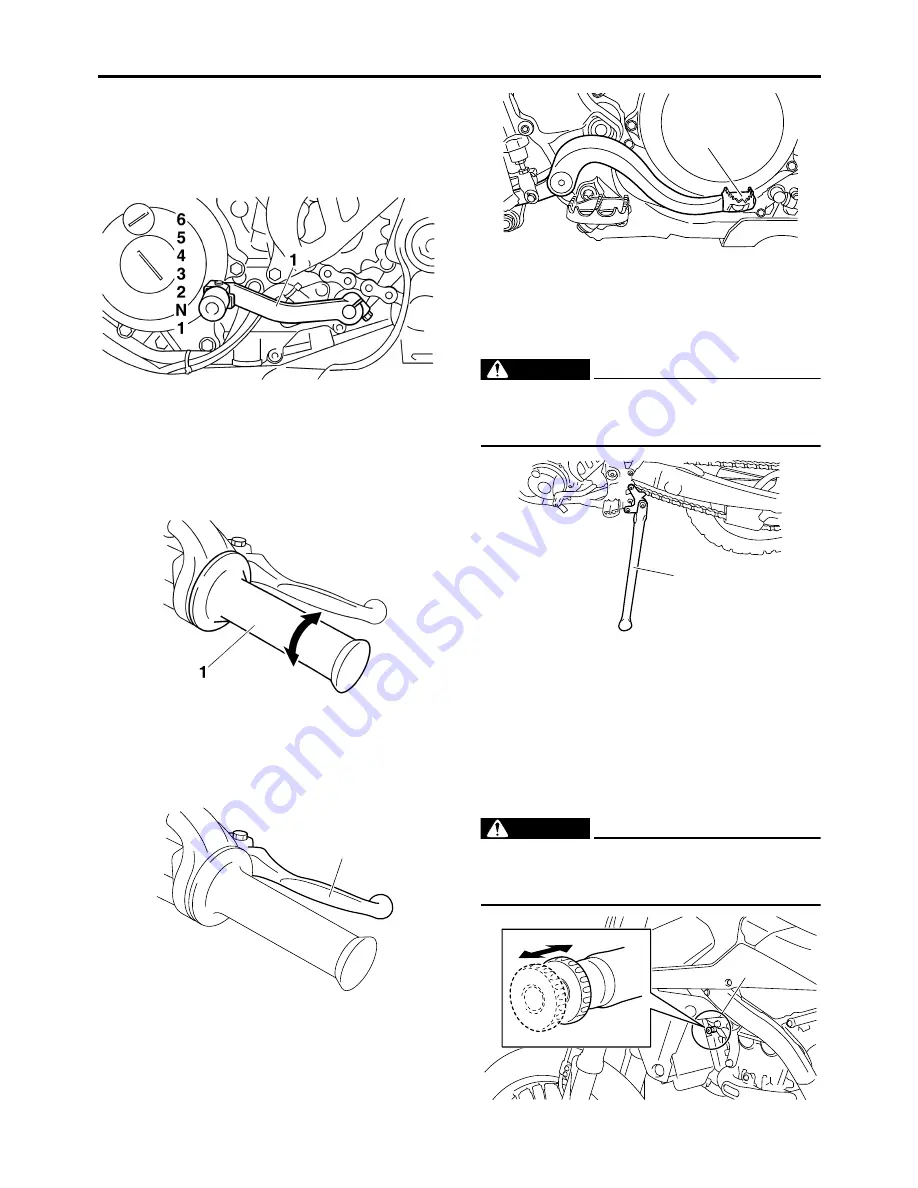
SHIFT PEDAL
The shift pedal “1” has adopted a method of 1
down & 5 ups (press-down & kick-ups).
Press it down for N (neutral) to 1st, and kick it
up for 2nd to 6th.
EASB29B034
THROTTLE GRIP
The throttle grip “1” is located on the right han-
dlebar. The throttle grip accelerates or deceler-
ates the engine. For acceleration, turn the grip
toward you; for deceleration, turn it away from
you.
EASB29B035
FRONT BRAKE LEVER
The front brake lever “1” is located on the right
handlebar. Pull it toward the handlebar to acti-
vate the front brake.
EASB29B036
REAR BRAKE PEDAL
The rear brake pedal “1” is in the right of the
chassis. Press down on the brake pedal to ac-
tivate the rear brake.
EASB29B037
SIDESTAND
This sidestand “1” is used to support only the
machine when standing or transporting it.
EWA
WARNING
• Never apply additional force to the sides-
tand.
• Hold up the sidestand before starting out.
EASB29B038
STARTER KNOB/IDLE ADJUSTING SCREW
Starting a cold engine requires a larger amount
of intake air, which is supplied by the starter
knob/idle screw “1”.
Pulling the knob toward “a” turns ON the start-
er, resulting in a larger amount of intake air.
Pushing the knob toward “b” turns OFF the
starter.
EWA
WARNING
While handling the starter knob/idle screw,
take care not to burn yourself on exhaust
pipes.
1
1
1
a
b
1
Summary of Contents for YZ 2018 Series
Page 6: ...EASB916006 YAMAHA MOTOR CORPORATION U S A YZ MOTORCYCLE LIMITED WARRANTY...
Page 10: ......
Page 40: ...MOTORCYCLE CARE AND STORAGE 1 28...
Page 64: ...LUBRICATION SYSTEM CHART AND DIAGRAMS 2 23...
Page 66: ...LUBRICATION SYSTEM CHART AND DIAGRAMS 2 25...
Page 68: ...LUBRICATION SYSTEM CHART AND DIAGRAMS 2 27...
Page 70: ...CABLE ROUTING DIAGRAM 2 29 EASB29B065 CABLE ROUTING DIAGRAM...
Page 72: ...CABLE ROUTING DIAGRAM 2 31...
Page 74: ...CABLE ROUTING DIAGRAM 2 33...
Page 76: ...CABLE ROUTING DIAGRAM 2 35...
Page 78: ...CABLE ROUTING DIAGRAM 2 37...
Page 80: ...CABLE ROUTING DIAGRAM 2 39...
Page 82: ...CABLE ROUTING DIAGRAM 2 41...
Page 84: ...CABLE ROUTING DIAGRAM 2 43...
Page 255: ...OIL PUMP AND BALANCER GEAR 5 58 a 2 10 b 2 9 1 b 5 3 a 4 10 5 9 3 E c d 6 7 8 8 b 6...
Page 276: ...TRANSMISSION 5 79...
Page 290: ...FUEL TANK 7 5 A Left B Right 1 1 A 0 mm 0 in B 1 1 15 mm 0 59 in...
Page 296: ...THROTTLE BODY 7 11...
Page 299: ......
Page 313: ...CHARGING SYSTEM 8 14...
Page 321: ...COOLING SYSTEM For JPN 8 22...
Page 351: ...FUEL PUMP SYSTEM 8 52 EASB29B345...
Page 352: ...ELECTRICAL COMPONENTS 8 53 ELECTRICAL COMPONENTS EASB29B346 9 10 11 1 3 2 4 5 6 7 8...
Page 354: ...ELECTRICAL COMPONENTS 8 55 11 10 9 2 3 1 6 7 8 4 5...
Page 356: ...ELECTRICAL COMPONENTS 8 57 EASB29B347 CHECKING THE SWITCHES 4 1 3 2 B B Sb B B B B B B B B...
Page 372: ...ELECTRICAL COMPONENTS 8 73 c Measure the fuel injector resistance...


