


FUEL INJECTION SYSTEM
8-29
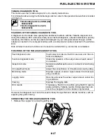
TROUBLESHOOTING DETAILS
This section describes the measures per fault code number displayed on the diagnostic tool. Check
and service the items or components that are the probable cause of the malfunction following the or-
der given.
After the check and service of the malfunctioning part have been completed, reset the diagnostic tool
display according to the reinstatement method.
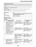
Fault code No.:
Fault code number displayed on the diagnostic tool when the engine failed to work normally.
Diagnostic code No.:
Diagnostic code number to be used when the diagnostic mode is operated.
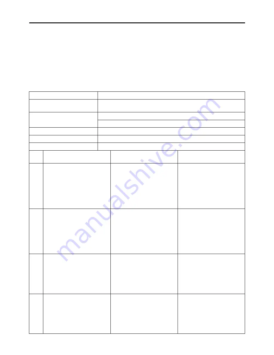
Fault code No.
12
Item
Crankshaft position sensor: no normal signals are received
from the crankshaft position sensor.
Fail-safe system
Unable to start engine
Unable to drive vehicle
Diagnostic code No.
—
Diagnostic tool display
—
Procedure
—
Item
Probable cause of malfunc-
tion and check
Maintenance job
Confirmation of service
completion
1
Connection of crankshaft po-
sition sensor coupler.
Check the locking condition
of the coupler.
Disconnect the coupler and
check the pins (bent or bro-
ken terminals and locking
condition of the pins).
Improperly connected
Connect the coupler securely
or repair/replace the wire har-
ness.
Crank the engine.
Fault code number is not dis-
played
Service is finished.
Fault code number is dis-
played
Go to item 2.
2
Connection of wire harness
ECU coupler.
Check the locking condition
of the coupler.
Disconnect the coupler and
check the pins (bent or bro-
ken terminals and locking
condition of the pins).
Improperly connected
Connect the coupler securely
or repair/replace the wire har-
ness.
Crank the engine.
Fault code number is not dis-
played
Service is finished.
Fault code number is dis-
played
Go to item 3.
3
Wire harness continuity.
Open or short circuit
Re-
place the wire harness.
Between the crankshaft posi-
tion sensor coupler and ECU
coupler.
black/blue–black/blue
gray–gray
Crank the engine.
Fault code number is not dis-
played
Service is finished.
Fault code number is dis-
played
Go to item 4.
4
Installed condition of crank-
shaft position sensor.
Check for looseness or
pinching.
Check the gap between the
crankshaft position sensor
and the pickup rotor.
Improperly installed sensor
Reinstall or replace the
sensor.
Refer to “GENERATOR AND
STARTER CLUTCH” on
page 5-59.
Crank the engine.
Fault code number is not dis-
played
Service is finished.
Fault code number is dis-
played
Go to item 5.
Summary of Contents for YZ 2018 Series
Page 6: ...EASB916006 YAMAHA MOTOR CORPORATION U S A YZ MOTORCYCLE LIMITED WARRANTY...
Page 10: ......
Page 40: ...MOTORCYCLE CARE AND STORAGE 1 28...
Page 64: ...LUBRICATION SYSTEM CHART AND DIAGRAMS 2 23...
Page 66: ...LUBRICATION SYSTEM CHART AND DIAGRAMS 2 25...
Page 68: ...LUBRICATION SYSTEM CHART AND DIAGRAMS 2 27...
Page 70: ...CABLE ROUTING DIAGRAM 2 29 EASB29B065 CABLE ROUTING DIAGRAM...
Page 72: ...CABLE ROUTING DIAGRAM 2 31...
Page 74: ...CABLE ROUTING DIAGRAM 2 33...
Page 76: ...CABLE ROUTING DIAGRAM 2 35...
Page 78: ...CABLE ROUTING DIAGRAM 2 37...
Page 80: ...CABLE ROUTING DIAGRAM 2 39...
Page 82: ...CABLE ROUTING DIAGRAM 2 41...
Page 84: ...CABLE ROUTING DIAGRAM 2 43...
Page 255: ...OIL PUMP AND BALANCER GEAR 5 58 a 2 10 b 2 9 1 b 5 3 a 4 10 5 9 3 E c d 6 7 8 8 b 6...
Page 276: ...TRANSMISSION 5 79...
Page 290: ...FUEL TANK 7 5 A Left B Right 1 1 A 0 mm 0 in B 1 1 15 mm 0 59 in...
Page 296: ...THROTTLE BODY 7 11...
Page 299: ......
Page 313: ...CHARGING SYSTEM 8 14...
Page 321: ...COOLING SYSTEM For JPN 8 22...
Page 351: ...FUEL PUMP SYSTEM 8 52 EASB29B345...
Page 352: ...ELECTRICAL COMPONENTS 8 53 ELECTRICAL COMPONENTS EASB29B346 9 10 11 1 3 2 4 5 6 7 8...
Page 354: ...ELECTRICAL COMPONENTS 8 55 11 10 9 2 3 1 6 7 8 4 5...
Page 356: ...ELECTRICAL COMPONENTS 8 57 EASB29B347 CHECKING THE SWITCHES 4 1 3 2 B B Sb B B B B B B B B...
Page 372: ...ELECTRICAL COMPONENTS 8 73 c Measure the fuel injector resistance...