BASIC SERVICE INFORMATION
1-9
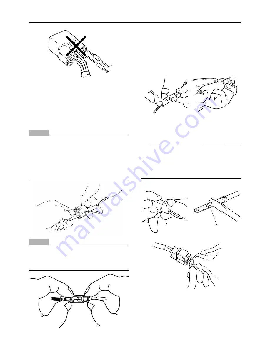
Checking the connections
Check the leads, couplers, and connectors for
stains, rust, moisture, etc.
1. Disconnect:
• Lead
• Coupler
• Connector
ECA
NOTICE
• When disconnecting a coupler, release the
coupler lock, hold both sections of the
coupler, and then disconnect the coupler.
• There are many types of coupler locks;
therefore, be sure to check the type of cou-
pler lock before disconnecting the cou-
pler.
ECA
NOTICE
When disconnecting a connector, do not
pull the leads. Hold both sections of the
connector, and then disconnect the con-
nector.
2. Check:
• Lead
• Coupler
• Connector
Moisture
Dry with compressed air.
Rust/stains
Connect and disconnect sev-
eral times.
3. Check:
• All connections
Loose connection
Connect properly.
TIP
• If the pin “1” on the terminal is flattened, bend
it up.
• After disassembling or assembling a coupler,
pull on the leads to make sure that they are in-
stalled securely.
1
Summary of Contents for YZ 2018 Series
Page 6: ...EASB916006 YAMAHA MOTOR CORPORATION U S A YZ MOTORCYCLE LIMITED WARRANTY...
Page 10: ......
Page 40: ...MOTORCYCLE CARE AND STORAGE 1 28...
Page 64: ...LUBRICATION SYSTEM CHART AND DIAGRAMS 2 23...
Page 66: ...LUBRICATION SYSTEM CHART AND DIAGRAMS 2 25...
Page 68: ...LUBRICATION SYSTEM CHART AND DIAGRAMS 2 27...
Page 70: ...CABLE ROUTING DIAGRAM 2 29 EASB29B065 CABLE ROUTING DIAGRAM...
Page 72: ...CABLE ROUTING DIAGRAM 2 31...
Page 74: ...CABLE ROUTING DIAGRAM 2 33...
Page 76: ...CABLE ROUTING DIAGRAM 2 35...
Page 78: ...CABLE ROUTING DIAGRAM 2 37...
Page 80: ...CABLE ROUTING DIAGRAM 2 39...
Page 82: ...CABLE ROUTING DIAGRAM 2 41...
Page 84: ...CABLE ROUTING DIAGRAM 2 43...
Page 255: ...OIL PUMP AND BALANCER GEAR 5 58 a 2 10 b 2 9 1 b 5 3 a 4 10 5 9 3 E c d 6 7 8 8 b 6...
Page 276: ...TRANSMISSION 5 79...
Page 290: ...FUEL TANK 7 5 A Left B Right 1 1 A 0 mm 0 in B 1 1 15 mm 0 59 in...
Page 296: ...THROTTLE BODY 7 11...
Page 299: ......
Page 313: ...CHARGING SYSTEM 8 14...
Page 321: ...COOLING SYSTEM For JPN 8 22...
Page 351: ...FUEL PUMP SYSTEM 8 52 EASB29B345...
Page 352: ...ELECTRICAL COMPONENTS 8 53 ELECTRICAL COMPONENTS EASB29B346 9 10 11 1 3 2 4 5 6 7 8...
Page 354: ...ELECTRICAL COMPONENTS 8 55 11 10 9 2 3 1 6 7 8 4 5...
Page 356: ...ELECTRICAL COMPONENTS 8 57 EASB29B347 CHECKING THE SWITCHES 4 1 3 2 B B Sb B B B B B B B B...
Page 372: ...ELECTRICAL COMPONENTS 8 73 c Measure the fuel injector resistance...


