


ENGINE
3-18
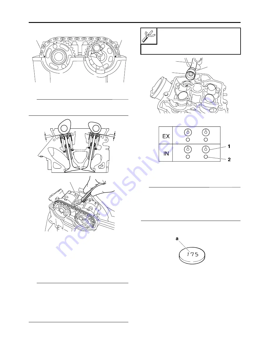
c. Measure the valve clearance “e” using a
thickness gauge “1”.
TIP
Record the measured reading if the clearance
is incorrect.
▲▲▲▲▲▲▲▲▲▲▲▲▲▲▲▲▲▲▲▲▲▲▲▲▲▲▲▲▲▲▲▲
5. Adjust:
• Valve clearance
▼▼▼▼▼▼▼▼▼▼▼▼▼▼▼▼▼▼▼▼▼▼▼▼▼▼▼▼▼▼▼▼
a. Remove the camshaft (intake and exhaust).
Refer to “CAMSHAFT” on page 5-11.
b. Remove the valve lifter “2” and the adjusting
pad “3” with a valve lapper “1”.
TIP
• Place a cloth in the timing chain space to pre-
vent adjusting pads from falling into the crank-
case.
• Identity each valve lifter and adjusting pad po-
sition very carefully so that they can be rein-
stalled in their original place.
c. Check the number on the originally installed
adjusting pad.
TIP
• The adjusting pad number “a” is indicated on
the top of the adjusting pad.
• For the number on the originally installed ad-
justing pad, convert the last digit of adjusting
pad number as per the below table.
d
c
e
e
1
Valve lapper
90890-04101
Valve lapping tool
YM-A8998
1
3
2
Summary of Contents for YZ 2018 Series
Page 6: ...EASB916006 YAMAHA MOTOR CORPORATION U S A YZ MOTORCYCLE LIMITED WARRANTY...
Page 10: ......
Page 40: ...MOTORCYCLE CARE AND STORAGE 1 28...
Page 64: ...LUBRICATION SYSTEM CHART AND DIAGRAMS 2 23...
Page 66: ...LUBRICATION SYSTEM CHART AND DIAGRAMS 2 25...
Page 68: ...LUBRICATION SYSTEM CHART AND DIAGRAMS 2 27...
Page 70: ...CABLE ROUTING DIAGRAM 2 29 EASB29B065 CABLE ROUTING DIAGRAM...
Page 72: ...CABLE ROUTING DIAGRAM 2 31...
Page 74: ...CABLE ROUTING DIAGRAM 2 33...
Page 76: ...CABLE ROUTING DIAGRAM 2 35...
Page 78: ...CABLE ROUTING DIAGRAM 2 37...
Page 80: ...CABLE ROUTING DIAGRAM 2 39...
Page 82: ...CABLE ROUTING DIAGRAM 2 41...
Page 84: ...CABLE ROUTING DIAGRAM 2 43...
Page 255: ...OIL PUMP AND BALANCER GEAR 5 58 a 2 10 b 2 9 1 b 5 3 a 4 10 5 9 3 E c d 6 7 8 8 b 6...
Page 276: ...TRANSMISSION 5 79...
Page 290: ...FUEL TANK 7 5 A Left B Right 1 1 A 0 mm 0 in B 1 1 15 mm 0 59 in...
Page 296: ...THROTTLE BODY 7 11...
Page 299: ......
Page 313: ...CHARGING SYSTEM 8 14...
Page 321: ...COOLING SYSTEM For JPN 8 22...
Page 351: ...FUEL PUMP SYSTEM 8 52 EASB29B345...
Page 352: ...ELECTRICAL COMPONENTS 8 53 ELECTRICAL COMPONENTS EASB29B346 9 10 11 1 3 2 4 5 6 7 8...
Page 354: ...ELECTRICAL COMPONENTS 8 55 11 10 9 2 3 1 6 7 8 4 5...
Page 356: ...ELECTRICAL COMPONENTS 8 57 EASB29B347 CHECKING THE SWITCHES 4 1 3 2 B B Sb B B B B B B B B...
Page 372: ...ELECTRICAL COMPONENTS 8 73 c Measure the fuel injector resistance...