


GENERATOR AND STARTER CLUTCH
5-61
EASB29B272
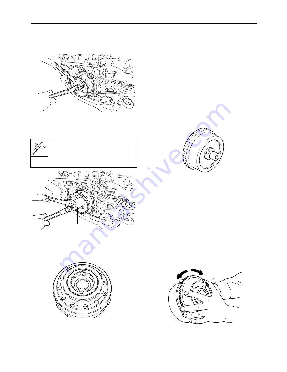
REMOVING THE GENERATOR
1. Remove:
• Generator rotor nut “1”
• Washer
2. Remove:
• Generator rotor “1”
(with the rotor puller “2”)
• Woodruff key
EASB29B273
CHECKING THE STARTER CLUTCH
1. Check:
• Starter clutch rollers
Damage/wear
Replace.
2. Check:
• Starter clutch idle gear
• Starter clutch gear
Burrs/chips/roughness/wear
Replace the
defective part (s).
3. Check:
• Starter clutch gear
Damage/pitting/wear
Replace the starter
clutch gear.
4. Check:
• Damper assembly
Damage/pitting/wear
Replace the damp-
er assembly.
Check the gear of the starter motor arma-
ture.
5. Check:
• Starter clutch operation
▼▼▼▼▼▼▼▼▼▼▼▼▼▼▼▼▼▼▼▼▼▼▼▼▼▼▼▼▼▼▼▼
a. Install the starter clutch drive gear “1” onto
the starter clutch and hold the starter clutch.
b. When turning the starter clutch drive gear
clockwise “A”, the starter clutch and the
starter clutch drive gear should engage, oth-
erwise the starter clutch is faulty and must
be replaced.
c. When turning the starter clutch drive gear
counterclockwise “B”, it should turn freely,
otherwise the starter clutch is faulty and
must be replaced.
▲▲▲▲▲▲▲▲▲▲▲▲▲▲▲▲▲▲▲▲▲▲▲▲▲▲▲▲▲▲▲▲
Rotor puller
90890-04142
Rotor puller
YM-04142
1
1
2
1
A
B
Summary of Contents for YZ 2018 Series
Page 6: ...EASB916006 YAMAHA MOTOR CORPORATION U S A YZ MOTORCYCLE LIMITED WARRANTY...
Page 10: ......
Page 40: ...MOTORCYCLE CARE AND STORAGE 1 28...
Page 64: ...LUBRICATION SYSTEM CHART AND DIAGRAMS 2 23...
Page 66: ...LUBRICATION SYSTEM CHART AND DIAGRAMS 2 25...
Page 68: ...LUBRICATION SYSTEM CHART AND DIAGRAMS 2 27...
Page 70: ...CABLE ROUTING DIAGRAM 2 29 EASB29B065 CABLE ROUTING DIAGRAM...
Page 72: ...CABLE ROUTING DIAGRAM 2 31...
Page 74: ...CABLE ROUTING DIAGRAM 2 33...
Page 76: ...CABLE ROUTING DIAGRAM 2 35...
Page 78: ...CABLE ROUTING DIAGRAM 2 37...
Page 80: ...CABLE ROUTING DIAGRAM 2 39...
Page 82: ...CABLE ROUTING DIAGRAM 2 41...
Page 84: ...CABLE ROUTING DIAGRAM 2 43...
Page 255: ...OIL PUMP AND BALANCER GEAR 5 58 a 2 10 b 2 9 1 b 5 3 a 4 10 5 9 3 E c d 6 7 8 8 b 6...
Page 276: ...TRANSMISSION 5 79...
Page 290: ...FUEL TANK 7 5 A Left B Right 1 1 A 0 mm 0 in B 1 1 15 mm 0 59 in...
Page 296: ...THROTTLE BODY 7 11...
Page 299: ......
Page 313: ...CHARGING SYSTEM 8 14...
Page 321: ...COOLING SYSTEM For JPN 8 22...
Page 351: ...FUEL PUMP SYSTEM 8 52 EASB29B345...
Page 352: ...ELECTRICAL COMPONENTS 8 53 ELECTRICAL COMPONENTS EASB29B346 9 10 11 1 3 2 4 5 6 7 8...
Page 354: ...ELECTRICAL COMPONENTS 8 55 11 10 9 2 3 1 6 7 8 4 5...
Page 356: ...ELECTRICAL COMPONENTS 8 57 EASB29B347 CHECKING THE SWITCHES 4 1 3 2 B B Sb B B B B B B B B...
Page 372: ...ELECTRICAL COMPONENTS 8 73 c Measure the fuel injector resistance...