HANDLEBAR
4-36
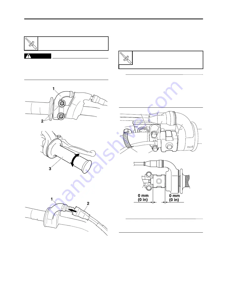
9. Install:
• Throttle cable housings “1”
• Screw (throttle cable housings) “2”
EWA
WARNING
After tightening the throttle cable housing
screws, check that the throttle grip “3”
moves smoothly. If it does not, retighten the
screws for adjustment.
10.Install:
• Rubber cover “1”
• Cover (throttle cable housings) “2”
11.Install:
• Start switch “1”
• Front brake master cylinder assembly “2”
• Front brake master cylinder holder “3”
• Bolt (brake master cylinder holder) “4”
• Clamp “5”
TIP
• Install the brake master cylinder holder with
the “UP” mark facing up.
• Install in order for the top of the front brake
master cylinder assembly to be level.
• First, tighten the upper bolt, then the lower
bolt.
12.Install:
• Clutch cable “1”
TIP
Before installation, apply the lithium-soap-
based grease to the clutch cable end.
Screw (throttle cable housings)
3.8 N·m (0.38 kgf·m, 2.8 lb·ft)
T
R
.
.
Front brake master cylinder hold-
er bolt
9 N·m (0.9 kgf·m, 6.6 lb·ft)
T
R
.
.
2
5
1
4
3
4
Summary of Contents for YZ 2018 Series
Page 6: ...EASB916006 YAMAHA MOTOR CORPORATION U S A YZ MOTORCYCLE LIMITED WARRANTY...
Page 10: ......
Page 40: ...MOTORCYCLE CARE AND STORAGE 1 28...
Page 64: ...LUBRICATION SYSTEM CHART AND DIAGRAMS 2 23...
Page 66: ...LUBRICATION SYSTEM CHART AND DIAGRAMS 2 25...
Page 68: ...LUBRICATION SYSTEM CHART AND DIAGRAMS 2 27...
Page 70: ...CABLE ROUTING DIAGRAM 2 29 EASB29B065 CABLE ROUTING DIAGRAM...
Page 72: ...CABLE ROUTING DIAGRAM 2 31...
Page 74: ...CABLE ROUTING DIAGRAM 2 33...
Page 76: ...CABLE ROUTING DIAGRAM 2 35...
Page 78: ...CABLE ROUTING DIAGRAM 2 37...
Page 80: ...CABLE ROUTING DIAGRAM 2 39...
Page 82: ...CABLE ROUTING DIAGRAM 2 41...
Page 84: ...CABLE ROUTING DIAGRAM 2 43...
Page 255: ...OIL PUMP AND BALANCER GEAR 5 58 a 2 10 b 2 9 1 b 5 3 a 4 10 5 9 3 E c d 6 7 8 8 b 6...
Page 276: ...TRANSMISSION 5 79...
Page 290: ...FUEL TANK 7 5 A Left B Right 1 1 A 0 mm 0 in B 1 1 15 mm 0 59 in...
Page 296: ...THROTTLE BODY 7 11...
Page 299: ......
Page 313: ...CHARGING SYSTEM 8 14...
Page 321: ...COOLING SYSTEM For JPN 8 22...
Page 351: ...FUEL PUMP SYSTEM 8 52 EASB29B345...
Page 352: ...ELECTRICAL COMPONENTS 8 53 ELECTRICAL COMPONENTS EASB29B346 9 10 11 1 3 2 4 5 6 7 8...
Page 354: ...ELECTRICAL COMPONENTS 8 55 11 10 9 2 3 1 6 7 8 4 5...
Page 356: ...ELECTRICAL COMPONENTS 8 57 EASB29B347 CHECKING THE SWITCHES 4 1 3 2 B B Sb B B B B B B B B...
Page 372: ...ELECTRICAL COMPONENTS 8 73 c Measure the fuel injector resistance...


