


4-3
CHAPTER 4 Adjustment
3-1
Absolute reset method
3-1-1
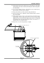
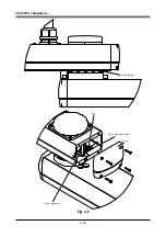
Sensor method (X-axis, Y-axis, and R-axis)
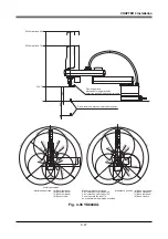
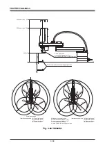
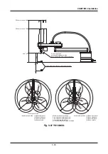
In the sensor method, the target axis is automatically operated for the absolute
reset, and the absolute reset is performed at the position where the proximity
sensor provided on the target axis detects the detection area (dog). The absolute
reset in the sensor method can be executed with the teaching pendant (MPB), RS-
232C communication, and dedicated input.
WARNING
Serious injury might occur from physical contact with the robot during opera-
tion. Never enter within the robot movement range during absolute reset.
!
CAUTION
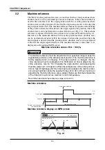
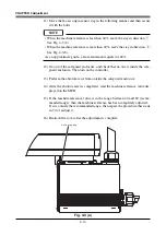
The origin cannot be detected in any axis which is not positioned on the plus
side from the origin (see Fig. 4-2) before starting the return-to-origin operation.
(Factory setting at shipment.) In this case, press the STOP key to interrupt the
return-to-origin operation, move the target axis to the plus side of the origin,
and reperform the origin return operation. If the return-to-origin operation is not
interrupted, the robot will continue the operation and may collide with the me-
chanical stopper or a peripheral device. Since a mechanical stopper is not pro-
vided in the R-axis, the wiring and piping installed on the end effecter may be
wound up by the operation.
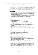
3-1-2
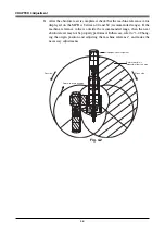
Stroke end method (Z-axis)
In the stroke end method, absolute reset is performed at a position slightly backed
off from the stroke end, after the Z-axis contacts the mechanical stopper and
stroke end is detected.
WARNING
Serious injury might occur from physical contact with the robot during opera-
tion. Never enter within the robot movement range during absolute reset.
Summary of Contents for YK-X Series
Page 1: ...User s Manual ENGLISH E YAMAHA SCARA ROBOT E35 Ver 1 08 YK XG YK X series ...
Page 2: ......
Page 6: ...MEMO ...
Page 10: ...MEMO ...
Page 12: ...MEMO ...
Page 30: ...MEMO ...
Page 36: ...MEMO ...
Page 46: ...3 10 CHAPTER 3 Installation Ground symbol M4 Ground terminal Fig 3 6 Ground terminal ...
Page 78: ...3 42 MEMO ...
Page 80: ...MEMO ...
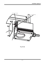
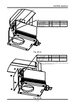
Page 101: ...4 21 CHAPTER 4 Adjustment Cover Elongated hole Y axis origin sensor stay Bolt Fig 4 8 a ...
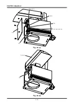
Page 102: ...4 22 CHAPTER 4 Adjustment Dog Hex nut Fig 4 8 b Bolt Y axis arm X axis arm Fig 4 8 c ...
Page 119: ...4 39 CHAPTER 4 Adjustment R End effector End effector Z Y X Fig 4 18 ...
Page 120: ...4 40 MEMO ...
Page 122: ...MEMO ...
Page 138: ...5 16 CHAPTER 5 Periodic Inspection M6 16 M5 16 X axis motor Base Fig 5 3 ...
Page 146: ...5 24 CHAPTER 5 Periodic Inspection M3 16 M4 18 X axis arm Fig 5 10 ...
Page 155: ...5 33 CHAPTER 5 Periodic Inspection O ring r M5 14 M6 16 R axis motor Fig 5 17 ...
Page 156: ...5 34 CHAPTER 5 Periodic Inspection M3 14 M3 16 O ring w Fig 5 18 ...
Page 161: ...CHAPTER 6 Increasing the robot operating speed 1 Increasing the robot operating speed 6 1 ...
Page 162: ...MEMO ...
Page 168: ...6 6 MEMO ...
Page 170: ...MEMO ...
Page 177: ...MEMO ...


