4-1
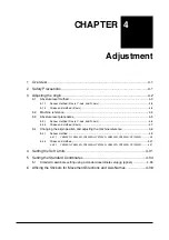
CHAPTER 4 Adjustment
1
Overview
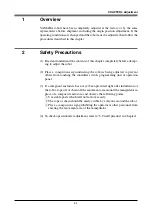
YAMAHA robots have been completely adjusted at the factory or by the sales
representative before shipment, including the origin position adjustment. If the
operating conditions are changed and the robot must be adjusted, then follow the
procedures described in this chapter.
2
Safety Precautions
(1) Read and understand the contents of this chapter completely before attempt-
ing to adjust the robot.
(2) Place a conspicuous sign indicating the robot is being adjusted, to prevent
others from touching the controller switch, programming unit or operation
panel.
(3) If a safeguard enclosure has not yet been provided right after installation of
the robot, rope off or chain off the movement area around the manipulator in
place of a safeguard enclosure, and observe the following points.
q
Use stable posts which will not fall over easily.
w
The rope or chain should be easily visible by everyone around the robot.
e
Place a conspicuous sign prohibiting the operator or other personnel from
entering the movement area of the manipulator.
(4) To check operation after adjustment, refer to "6. Trial Operation" in Chapter 1.
Summary of Contents for YK-X Series
Page 1: ...User s Manual ENGLISH E YAMAHA SCARA ROBOT E35 Ver 1 08 YK XG YK X series ...
Page 2: ......
Page 6: ...MEMO ...
Page 10: ...MEMO ...
Page 12: ...MEMO ...
Page 30: ...MEMO ...
Page 36: ...MEMO ...
Page 46: ...3 10 CHAPTER 3 Installation Ground symbol M4 Ground terminal Fig 3 6 Ground terminal ...
Page 78: ...3 42 MEMO ...
Page 80: ...MEMO ...
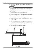
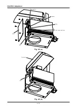
Page 101: ...4 21 CHAPTER 4 Adjustment Cover Elongated hole Y axis origin sensor stay Bolt Fig 4 8 a ...
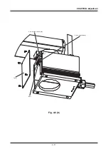
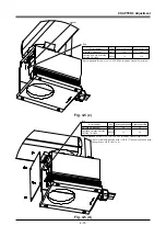
Page 102: ...4 22 CHAPTER 4 Adjustment Dog Hex nut Fig 4 8 b Bolt Y axis arm X axis arm Fig 4 8 c ...
Page 119: ...4 39 CHAPTER 4 Adjustment R End effector End effector Z Y X Fig 4 18 ...
Page 120: ...4 40 MEMO ...
Page 122: ...MEMO ...
Page 138: ...5 16 CHAPTER 5 Periodic Inspection M6 16 M5 16 X axis motor Base Fig 5 3 ...
Page 146: ...5 24 CHAPTER 5 Periodic Inspection M3 16 M4 18 X axis arm Fig 5 10 ...
Page 155: ...5 33 CHAPTER 5 Periodic Inspection O ring r M5 14 M6 16 R axis motor Fig 5 17 ...
Page 156: ...5 34 CHAPTER 5 Periodic Inspection M3 14 M3 16 O ring w Fig 5 18 ...
Page 161: ...CHAPTER 6 Increasing the robot operating speed 1 Increasing the robot operating speed 6 1 ...
Page 162: ...MEMO ...
Page 168: ...6 6 MEMO ...
Page 170: ...MEMO ...
Page 177: ...MEMO ...

